The article provides an overview of fuel cell, explaining their function, benefits, and applications in clean energy and transportation. It also outlines the main types of fuel cells—PEMFC, SOFC, MCFC, PAFC, and AFC—highlighting their working principles, materials used, and suitability for different applications.
Fuel Cell Definition
Fuel cells are modular, environmentally clean, sustainable, efficient, and of a versatile technology. Fuel cell systems have been demonstrated for clean energy, transportation, and various other applications.
A fuel cell is a device that generates electricity through a chemical reaction. It has two electrodes, an anode, and a cathode, with an electrolyte sandwiched between them.
Hydrogen is the basic fuel for fuel cells and exposing the anode to hydrogen and the cathode to oxygen derived from air results in electricity being produced without combustion of any form.
Water and heat are the only by-products when pure hydrogen is used as the fuel source. Although hydrogen is considered the primary fuel source for fuel cells, the process of fuel reforming allows for the extraction of hydrogen from other fuels including methanol, natural gas, petroleum, or renewable hydrocarbon sources.
The first fuel cell was developed in 1839 by Sir William Grove, a Welsh judge, and a scientist.
Fuel cells are generally classified according to the nature of the electrolyte, each type requiring a particular type of electrolyte material. Also, each fuel cell type has its own unique characteristics and merits for a given application.
Table 1 lists different fuel cells, operating temperature, and electrical efficiency range.
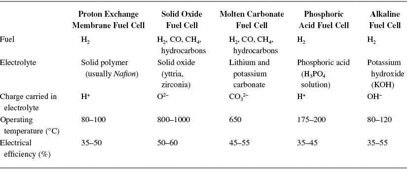
TABLE 1 Fuel Cell Technologies
Proton Exchange Membrane Fuel Cell
The heart of the proton exchange membrane fuel cell (PEMFC) is the proton-conducting solid polymer electrolyte membrane in the form of a thin, permeable sheet. It is surrounded by two layers: a diffusion and a reaction layer.
Under constant supply of hydrogen and oxygen, the hydrogen diffuses through the porous anode and diffusion layer up to the platinum catalyst. The reason for the diffusion current is the tendency of hydrogen-oxygen reaction.
In the reaction layer supported by the catalyst and at a temperature of about 80 °C–100 °C, protons and electrons split as represented by H2 → 2H+ + 2e−.
The hydrogen ion passes through the polymer membrane on its way to the cathode, while the only possible way for the electrons is through an outer circuit. At the three-phase boundary between cathode and electrolyte, the hydrogen ions react with the oxygen, which has diffused through the porous cathode and the electrons from the outer electrical circuit, to form water.
The resultant reaction is 2H+ + ½O2 + 2e− → H2O. Excess airflow on the cathode side helps to remove the water resulting from the reaction. The overall fuel cell reaction is 2H2 + O2 → 2H2O + heat.
The efficiency of the PEMFC is about 40%–50% and its operating temperature is about 80°C–100°C. Owing to the low-temperature operation, faster response to load transients, and short start-up time (less than a minute), the PEMFC is suitable for propulsion applications.
Several industries are developing this type of fuel cells for propulsion and other applications.
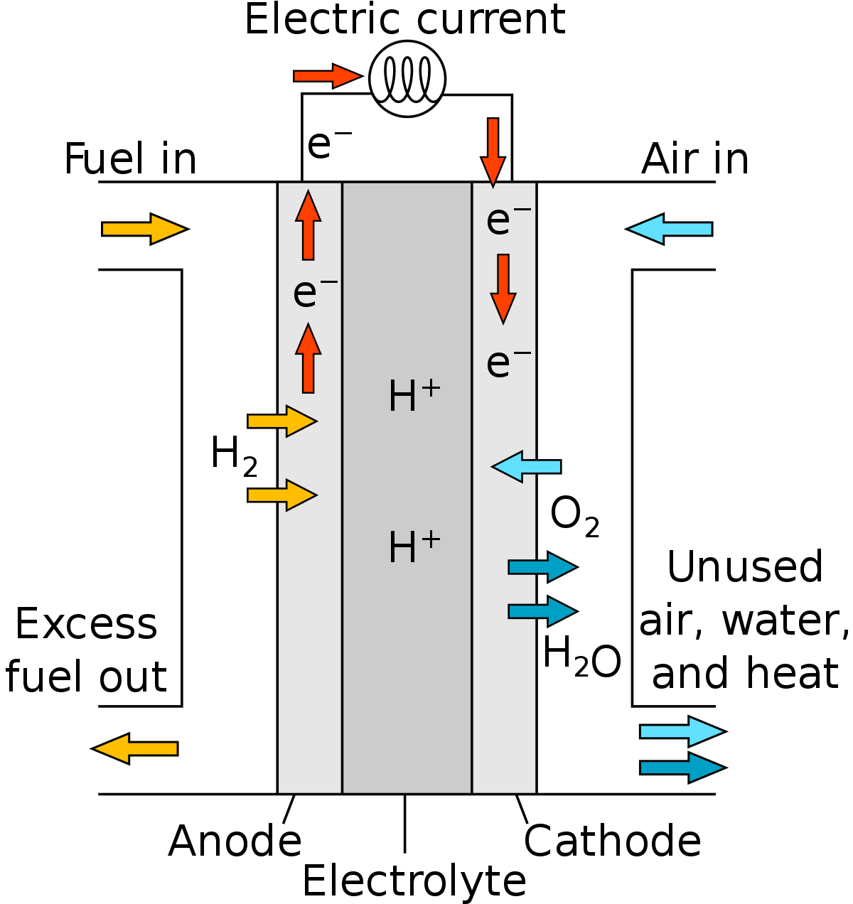
Diagram of a PEM fuel cell (Source: WikiPedia)
However, the PEMFC requires pure hydrogen, and drastic performance degradation occurs even from a small amount of carbon monoxide, resulting in the poisoning of the electrodes.
A sophisticated water management system is also required because of the continuous water generation at the cathode and to keep the membrane at a certain humidity level.
Although significant research has been done to reduce the level of platinum coating on the electrodes, this requirement makes the proton exchange membrane (PEM)-based systems relatively expensive.
PEMFCs operate at low temperatures (less than 100 °C), making them temperature compatible with many of today’s automotive systems and also allowing for a faster start-up.
However, due to a relatively small temperature gradient to the ambient atmosphere, the waste heat produced is low grade and requires large heat exchangers.
Also, for the PEM electrolyte to operate properly it must be hydrated, resulting in the need for sophisticated water management and the humidification of the incoming fuel and oxygen flows. This hydration also causes issues because automobiles must operate below the freezing point of water, with typical specifications for today’s automotive components being in the range of –30 °C to –40 °C.
Finally, to achieve the high power density, the incoming reactant gases are pressurized to 2–3 atmospheres to increase power output, resulting in the need for high-pressure and high-flow air compressors. PEMFCs have been demonstrated in systems with the size ranging from 1 W to 250 kW.
Solid Oxide Fuel Cell
A solid oxide fuel cell (SOFC) usually uses a hard-ceramic material of solid zirconium oxide and a small amount of yttria, instead of a liquid electrolyte, allowing operating temperatures to reach about 1000 °C.
The solid electrolyte is coated on both sides with specialized porous electrode materials. The hydrogen is supplied at the anode, and oxygen, usually from the air, at the cathode.
At these high operating temperatures, oxygen ions (with a negative charge) migrate through the electrolyte to the anode.
Electrons generated at the anode travel through an external load to the cathode, completing the circuit and supplying electric power along the way.
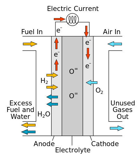
Diagram of a solid-oxide fuel cell (Source: Wikipedia)
SOFC requires a simple reforming process and may not need an external reformer. SOFC operates at extremely high temperatures in the range of 700 °C–1000 °C and hence has less compelling requirements for reformate quality and uses carbon monoxide as fuel.
High-grade heat exhaust of SOFC allows for smaller heat exchangers and the cogeneration option to produce extra power, thus increasing the overall system efficiency.
Because the electrolyte is in a solid state and does not require hydration, water management is not a concern.
The by-product is steam rather than liquid water, which must be drained out in a PEM system.
In addition, fuel versatility makes SOFCs suitable for large to very large stationary power generation applications.
SOFC has also been demonstrated as an auxiliary power unit (APU) in automotive systems. The SOFC is very suitable for combined heat and power (CHP) and for hybrid power generation (or cogeneration), where the exhaust of the SOFC can be used to run a turbine to generate additional electric power.
The start-up time of the SOFC system is long because of its high-temperature operation and therefore is not suitable for propulsion applications.
Molten Carbonate Fuel Cell
Molten carbonate fuel cell (MCFC) uses high-temperature compounds of salt (like a mixture of sodium and lithium or magnesium or lithium and potassium) carbonates (chemically CO3) as the electrolyte and is the only fuel cell that requires CO2 supply. Their nickel electrode catalysts are inexpensive compared to the platinum used in PEMFC.
Carbonate ions from the electrolyte are used up in the reactions at the anode, making it necessary to compensate by injecting carbon dioxide at the cathode.
Diagram of a Molten carbonate fuel cell (Source: Wikipedia)
The operating temperature of the MCFC is about 650 °C. Due to the high-temperature operation, MCFC is less prone to carbon monoxide “poisoning” than lower-temperature fuel cells, which makes coal-based fuels more attractive for this type of fuel cell.
Like SOFC, it is best suited for stationary power generation applications and cogeneration. Units with output up to 2 megawatts (MW) have been constructed, and designs exist for units up to 100 MW.
MCFC also has a long start-up time to reach the operating temperature and has a lower power density than SOFC and is not suitable for propulsion application.
Phosphoric Acid Fuel Cell
Phosphoric acid fuel cell (PAFC) uses phosphoric acid as the electrolyte and the operating temperature of these cells is about 200 °C. It uses platinum electrode catalysts to withstand the corrosive acid effects.
Because of about 200 °C operation, PAFCs can tolerate a carbon monoxide concentration of about 1.5%, which broadens the choice of fuels they can use. However, the sulfur needs to be removed from the fuel.
PAFC was the first fuel cell to cross the commercial threshold.
The United Technology Corporation developed and placed a number of PAFC-based 50–200 kW range power units in operation for stationary power applications in the United States and overseas.
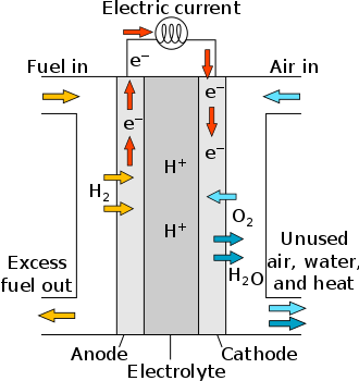
Diagram of a Phosphoric acid fuel cell (Source: Wikipedia)
Most fuel cell systems that were sold before 2001 for the stationary power generation application used PAFC technology.
Alkaline Fuel Cell
Alkaline fuel cells (AFCs) generally use a solution of potassium hydroxide in water as their electrolyte, and the operating temperature is 150 °C–200 °C.
AFC uses platinum electrode catalysts. The hydroxyl ions (OH−) migrate from the cathode to the anode. At the anode, hydrogen ions react with the OH− ions to produce water and release electrons.
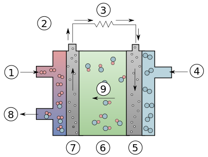
Diagram of an Alkaline Fuel Cell. 1: Hydrogen 2: Electron flow 3: Load 4: Oxygen 5: Cathode 6: Electrolyte 7: Anode 8: Water 9: Hydroxyl Ions (Source: Wikipedia)
Electrons generated at the anode supply electric power to an external circuit and then return to the cathode. At the cathode, the electrons react with oxygen and water to produce more hydroxyl ions that diffuse into the electrolyte.
AFCs are highly reliable and efficient and are being used in space applications. NASA selected AFCs for their space shuttle fleet and the Apollo program to provide both electricity and drinking water.
Fuel Cell Types Key Takeaways
Fuel cells represent a critical advancement in clean energy technologies due to their high efficiency, environmental benefits, and adaptability across a wide range of applications. Each type of fuel cell—PEMFC, SOFC, MCFC, PAFC, and AFC—offers unique advantages tailored to specific needs, from portable and automotive uses to large-scale stationary power generation and space missions. Their ability to produce electricity with minimal emissions, particularly when using pure hydrogen, supports global efforts toward reducing carbon footprints and transitioning to sustainable energy systems.