The focus in this section is on battery management systems (BMS) and includes topics related to the SOC, SOH, and state of life (SOL).
An Energy Storage Management System (ESMS) is typically employed in order to ensure optimal and safe operation of devices, such as batteries and ultracapacitors.
A typical ESMS configuration includes an effective cell balancing mechanism; cooling and ventilation; data acquisition and controls; communications and interfaces between subsystems and with the power system; protections; for example, to overvoltage and short circuit; condition monitoring for SOC and state of health (SOH); and temperature.
The management systems for both batteries and ultracapacitors share the same basic principles, but batteries require additional care as their lifetime and safe performance are highly sensitive to parameters like high temperatures, DOD, and current rate.
Battery Management System Categories
In terms of functionality, Battery Management Systems (BMSs) may be divided into three categories: centralized, modular or master-slave, and distributed.
In a centralized BMS, parameters such as voltage, current, and temperature are measured for individual cells and sent to the main BMS board. This topology is compact, cost-efficient, and well suited for troubleshooting.
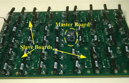
In a modular BMS, slave cards collect the data from each cell and send them to a master card, which coordinates the management of the entire system (Figure 1). This topology enables a modular expansion for larger-sized packs.
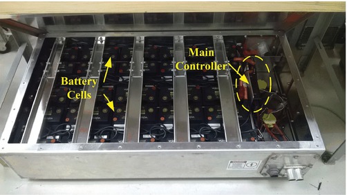
In a distributed BMS, as shown in Figure 2, each cell has its own individual electronic board and the main controller, which is responsible for communications and necessary computations.
Figure 1 A modular BMS topology where several slave boards collect cells data and send it to the master board.
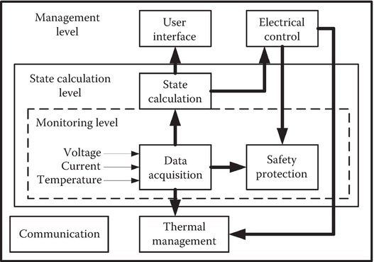
Xing et al. have proposed a generic BMS structure in which various sensors are installed in the battery pack and gather real-time data for system safety and battery state calculation.
The data are employed for cell balancing and thermal management, protection, and state determination, which in turn are used for the electrical control, as shown in Figure 3.
Figure 2 A distributed BMS: each cell sends the data to the main controller.
Figure 3 Block diagram of a typical Battery Management System (BMS).
State of Charge (SOC)
The SOC is an indicator of the amount of remaining energy or charge available in a battery as a fraction of the nominal value that is rated value of capacity.
Since the SOC is not measurable directly, it needs to be evaluated based on other parameters that significantly affect the SOC like battery current, temperature, and the number of lifetime cycles.
It should be noted that the maximum capacity of a battery gradually and nonlinearly degrades over time, making it very challenging to extract and estimate the exact value of the SOC.
Coulomb Counting Method for SOC
The most common approach for estimating SOC is Coulomb counting, according to which the capacity of the battery is calculated by integrating the battery current over time. This method is well suited for Li-ion batteries, which have high columbic efficiency.
The accuracy of this method is highly dependent on the initial value of the SOC and the nominal capacity of the battery, which is decreasing as battery ages.
In order to reduce the possible initial SOC error and also to compensate for the possible accumulated error due to integration, the SOC estimation based on the open-circuit voltage (OCV) versus SOC table, a table in which each OCV value is associated with a SOC value, has been proposed.
Although the online (real-time) measurement of OCV has its own challenges, computationally intelligent methods, such as neural and fuzzy algorithms, have been developed in this respect to estimating SOC.
Because these methods are very sensitive to the model error and disturbance, the estimated results may fluctuate widely.
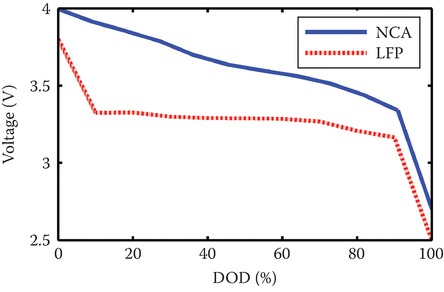
Furthermore, the OCV versus SOC or DOD curves for some battery chemistries are almost flat for most of the operating ranges, due to their cathode chemistry (Figure 4).
Some types, such as LFP, also have a very long voltage relaxation time, limiting the practical application of this technique.
Figure 4 Open-circuit voltage (OCV) versus DOD for NCA and LFP types of Li-ion batteries.
Kalman Filter (EKF) For SOC
The extended Kalman filter (EKF) is widely used for estimating SOC. The EKF approach is highly sensitive to the accuracy of the battery model and parameter values, and therefore, special care should be taken in order to avoid significant error and divergence.
To reduce the sensitivity to the model parameters, an adaptive EKF was proposed. Several other methods, including robust H∞ and sliding mode observers, and support vector machine techniques have been employed to estimate the SOC of batteries.
State of Health (SOH)
The SOH has several definitions, such as the maximum charge that can be released after the battery has been fully charged, or the battery’s capacity of storing energy and preserving charge for long periods, or the remaining battery capacity for the current cycle as compared to the original battery capacity.
The SOH can also be defined as a set of indicators or diagnostic flags, which reflect the health status and physical condition of the battery, such as loss of rated capacity.
The value of SOH is beneficial for applications like HEV and EV, where it is used as an indication of specified power or to estimate the driving range.
Similar to the SOC problem, several techniques have been developed for SOH estimation, including EKF, adaptive observer, and probabilistic neural networks.
Measuring the internal equivalent DC resistance of a cell, which increases with capacity degradation, is another characterization tool for SOH.
State of Life (SOL)
The SOL is defined as the remaining useful life (RUL) of a battery or as the time when a battery should be replaced.
This indicator is considered from the design stage in order to plan ahead maintenance and replacement schedules, prevent failures during operation, and increase the reliability and availability of an ESS.
Cell Balancing Systems
In order to achieve higher voltage and current, a battery pack consists of several cells, which are connected in series and parallel layouts, respectively.
The cells in a string could have different SOC levels due to several internal and external sources of unbalancing, which may result in different capacity fading rates between cells.
Internal imbalances include different self-discharging resistance and impedance, and external causes may include thermal variation across the string.
During charging or discharging, imbalances in between cells may lead to extreme voltages and hence severe overcharging and over-discharging that could seriously damage cells, reduce useful lifetime, and even cause fires and explosions.
Therefore, an effective battery cell balancing system, which maintains the SOC of the cells at the same level, is an important feature of any BMS.
Cell balancing systems are either passive or active.
According to the typical passive balancing methods, the extra energy of an imbalanced cell is released by increasing the cell body temperature, a technique that is useful especially for small battery packs with low voltage.
This technique is relatively straightforward and inexpensive to implement, but its applicability is mostly limited to cells that do not damage severely due to overcharging.
The active balancing technique utilizes an active circuit to distribute as evenly as possible the energy among the cells.
Active balancing techniques are employed in several different ways including shunting and shuttling and energy converting method.
From the energy flow point of view, active balancing methods comprise dissipative and non-dissipative methods.
The extra energy in dissipative methods is wasted as heat across a resistor, while in non-dissipative techniques, the excess energy is distributed among the string cells, leading to a higher system efficiency.


