The article discusses the function and components of distribution switchboard and panelboard, explaining their roles in power distribution within buildings, including the protective devices, overcurrent protection, and control mechanisms involved. It also covers the layout and installation requirements of these systems, ensuring safety and compliance with regulations.
Electrical power is delivered to industrial, commercial, and residential buildings through a distribution and transmission system. Once the power is delivered to a building, it is up to the building electrician to further distribute the power to where it is required within the building.
Switchboard Definition
A switchboard is a large floor-mounted panel or assembly of panels in which electrical switches, OCPDs, buses, and instruments are mounted. See Figure 1. Switchgear is any high-powered electrical device that switches or interrupts devices or circuits in a building distribution system.
The terms switchgear and switchboards are often used interchangeably or when referring to both switchgear and switchboard equipment. A switchboard is typically the link between the power delivered to a building or property and the start of the building’s power distribution system.
The switchboard may be the last point on the power distribution system for the utility and the beginning of the distribution system for the building electrician.
Switchboards are rated by the manufacturer for a maximum voltage and current output. For example, a switchboard may have a 50 V rating and a bus rating up to 5000 A.
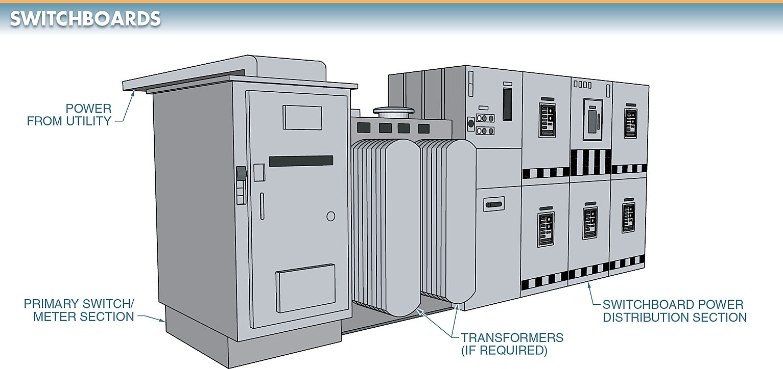
Figure 1. Switchboards are large floor-mounted panels or assemblies of panels in which electrical switches, OCPDs, buses, and instruments are mounted.
In addition to dividing the incoming power, a switchboard may contain all the equipment needed for controlling, monitoring, protecting, and recording the functions of the substation. Switchboards are designed for use in service-entrance and distribution.
A service-entrance switchboard has space and mounting provisions for metering equipment (as required by the local power company), overcurrent protection, and a means of disconnect for the service conductors. Provisions for grounding the service neutral conductor when a ground is needed are also provided.
Distribution Switchboard
A distribution switchboard contains the protective devices and feeder circuits required to distribute the power throughout a building. A distribution switchboard may contain either circuit breakers or fused switches.
A distribution switchboard has space and mounting provisions required by the local power company. Building power distribution systems are used to deliver the required type (DC, 1φ, or 3φ) and level (70 V, 230 V, 45 V, etc.) of power to the loads connected to the system.
Metering equipment for the power used by the building’s tenants is also installed at this location. To meter the incoming power, the switchboard must have a watt-hour meter to measure power usage.
Metering equipment is always located on the incoming line side of the disconnect. The metering equipment compartment cover is sealed to prevent power from being tapped ahead of the power company metering equipment. See Figure 2.
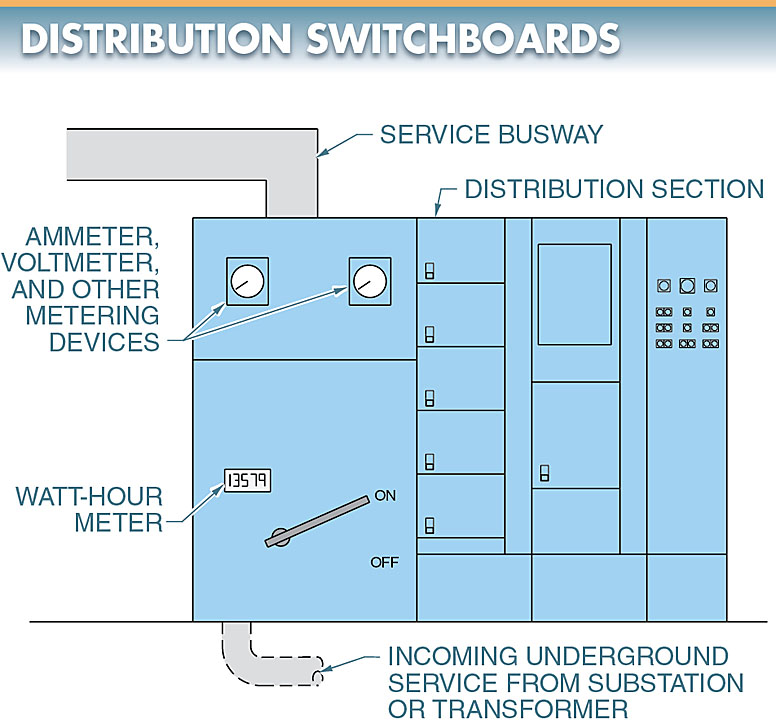
Figure 2. A distribution switchboard contains the protective devices and feeder circuits required to distribute power throughout a building.
Other meters and indicator lights, such as voltmeters, ammeters, and watt meters, may also be built into the meter equipment compartment. In most cases, these components are optional, depending on the application and the plant requirements.
A voltmeter is used to indicate the various incoming and outgoing voltages to the maintenance personnel. An ammeter is used to indicate the various current levels throughout the system. A wattmeter is used to indicate the power used throughout the system.
These instruments can be indicating types, record types, or a combination of both types. Recording instruments are used to track various values during a period of time.
In addition to measuring the voltage, current, and power of a system, a switchboard also controls the power. Control is achieved through the use of switches, fuses, circuit breakers, and overcurrent and overvoltage relays that can disconnect the power. These devices protect the distribution system in the event of a fault.
Switchboards that have more than six switches or circuit breakers must include a main switch to protect or disconnect all circuits.
Switchboards with more than one but not more than six switches or circuit breakers do not require the main switch. In a switchboard with more than six switches or breakers, the service-entrance section of the switchboard may have feeder circuits added to the rated capacity of the main.
A switchboard with the main section can easily contain more than one distribution system. The system requirement depends on the number of feeder circuits entering the building. More information is available in NEC® Article 240.
In addition to distributing the power throughout a building, the distribution section of a switchboard may contain provisions for motor starters and other control devices. See Figure 3.
The addition of starters and controls to the switchboard allows for motors to be connected to the switchboard. This combination can be used when the motors to be controlled are located near the switchboard. The combination also allows for high-current loads such as motors to be connected to the source of power without further power distribution.
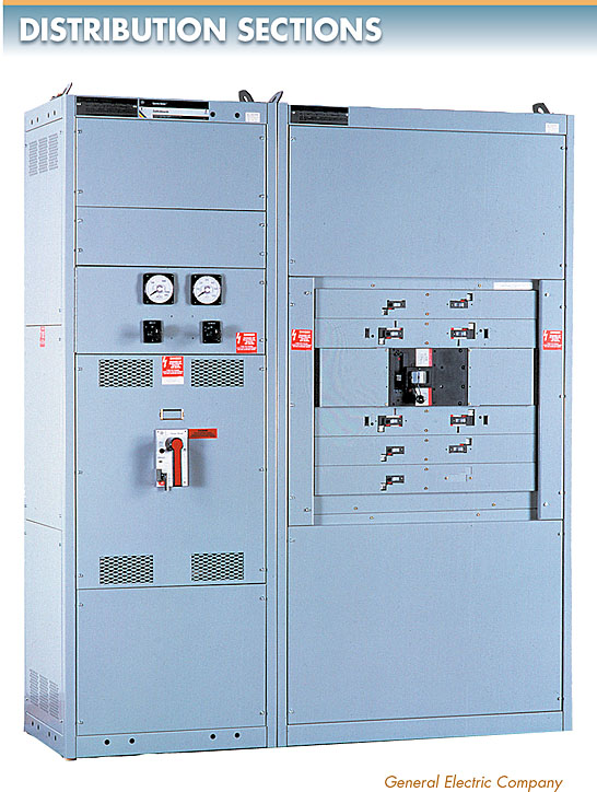
Figure 3. The distribution section of a switchboard may contain provisions for motor starters and other devices.
Panelboards and Branch Circuits
A panelboard is a wall-mounted distribution cabinet containing a group of overcurrent and short-circuits protective devices for lighting, appliance, or power distribution branch circuits.
Wall-mounted panelboards are discernible from switchboards because switchboards are normally freestanding. See Figure 4.
A panelboard is normally supplied with power by a switchboard and further divides the power distribution system into smaller parts.
Panelboards are the part of the distribution system that provides the last centrally located protection for the final power run to the load and its control circuitry. Panelboards are classified according to their use in the distribution system.
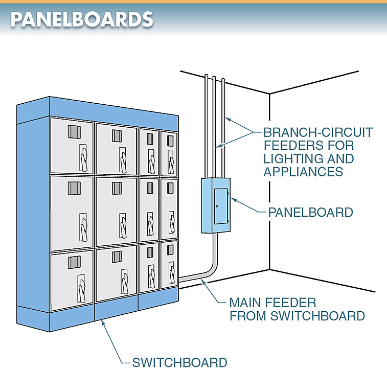
Figure 4. A panelboard is a wall-mounted distribution cabinet containing overcurrent and short-circuits protection devices.
A panelboard provides the required circuit control and overcurrent protection for all circuits and power- consuming loads connected to the distribution system. See Figure 5.
Panelboards are located throughout a plant or building, providing the necessary protection for the branch circuits that feed the loads.
A branch circuit is the portion of the distribution system between the final OCPD and the outlet or load connected to it. The basic requirements for panelboards and OCPDs are given in the NEC® Articles 240 and 403 and must be met for individual applications. In addition, local, city, and country regulations must also be met.
OCPDs used for protecting branch circuits include fuses or circuit breakers. OCPDs must provide for proper overload and short-circuit protection. The size (in amperes) of the OCPD is based on the rating of the panelboard and load.
OCPDs must protect the load and be within the rating of the panelboard. If the OCPD exceeds the capacity of the busbars in the panelboard, the panelboard is undersized for the load(s) that are to be connected.
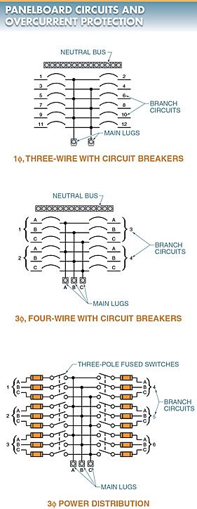
Figure 5. A panelboard provides the required circuit control and overcurrent protection for all circuits and power-consuming loads connected to the distribution system.
Panelboard Installation
Panelboards are the main place where most indoor electrical circuits begin. The panelboard must have a sufficient current and voltage rating and must be properly installed and grounded.
An electrical shock or fire is possible if the panelboard is not properly installed and grounded. In addition, the system can be overloaded and a fire can result if the panelboard is not properly sized.
All panelboard installations should follow NEC® and NFPA requirements. For example, NEC® Articles 403 and 404 cover the installation of switchboards and panelboards. See Figure 6. These requirements protect persons working around panelboards, help prevent fires, and reduce the chance of an electrical shock.
Tech Fact
A neutral ground connection is made by connecting the neutral bus in the main panelboard to the ground bus with a main bonding jumper.
The ground bus is connected to the earth grounding system. Additional neutral-to-ground connections should not be made in any other subpanels, receptacles, or equipment.
If a neutral-to-ground connection is made, a parallel path for the normal return neutral current is created. This will produce an unsafe condition because current will flow through all the grounds and can cause electrical shocks.

Figure 6. NEC® Article 403 covers the installation of panelboards.
Distribution Switchboard Key Takeaways
Distribution switchboards and panelboards play a critical role in the safe and efficient distribution of electrical power within buildings. These systems not only ensure the proper division of power from the main source to various parts of the building but also provide essential protection through overcurrent devices and circuit control mechanisms. Their design, installation, and compliance with regulations such as NEC® standards are crucial to minimizing risks like electrical shock or fire. By incorporating features like metering, circuit breakers, and motor starters, these systems are adaptable to different building requirements, supporting both residential and industrial applications. Overall, these components are essential in ensuring the safety, functionality, and reliability of electrical systems within buildings, making them indispensable in power distribution.