The article provides an overview of various types of resistors—such as carbon composition, thin and thick film, wire wound, adjustable resistors, potentiometers, and thermistors—and explains their construction, functions, and applications. It also covers the resistor color code system used to identify resistance values and tolerances on small resistors.
One of the most common components encountered in the study of electronics is the resistor. The resistor is used to create desirable voltage drops and limit current values in electronic circuitry. Figure 1 shows several molded composition, fixed resistors. They are manufactured in many sizes and shapes. The schematic symbol for a fixed resistor is also shown.
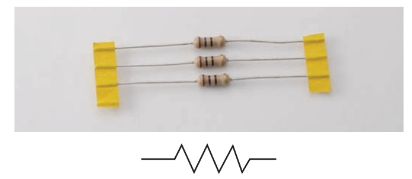
Figure 1. Group of carbon composition resistors and the fixed resistor symbol.
The chemical makeup that causes resistance is accurately controlled in the resistor manufacturing process. Resistor values can be purchased in a range of values from less than 1 ohm to over 22 mega-ohms.
The physical size and material used for resistance is rated in watts. A resistor’s wattage rating refers to the resistor’s ability to safely dissipate heat. Heat is generated by electrons flowing through the resistor. Common wattage sizes range from 1/4 watt to 25 watts. Resistors are grouped by ohms and watt sizes. See Figure 2.
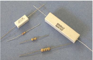
Figure 2. The physical size of a resistor can vary according to wattage rating. The higher the wattage, the larger the resistor. The largest shown is 20 watts, and the smallest is 1/8 watt.
When purchasing a resistor, the desired resistance and wattage rating must be specified. For example: 1000 ohms and the watt size, 1/4 watt, 1/2 watt, or 2 watts, etc. In each watt size, the resistance value would be the same. See Figure 3 to examine the construction of a molded composition resistor.
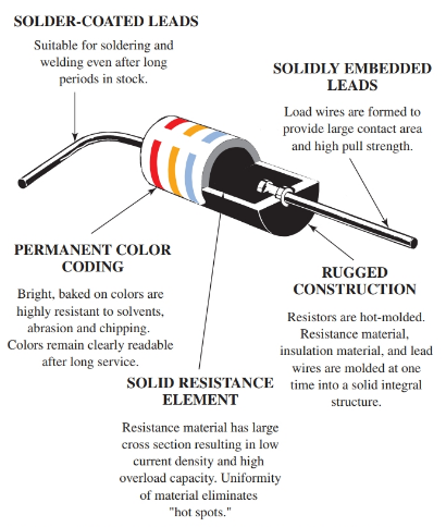
Figure 3. Cutaway of a carbon composition resistor. (Allen-Bradley)
Thin Film Resistor
Another type of small wattage, fixed value resistor is the thin film resistor. The thin film resistor is similar to the molded composition resistor in appearance and function. However, the thin film resistor is made by depositing a resistance material on a glass or ceramic tube. A photographic process is used to deposit this film. Leads with caps are fitted over each end of the tube to make the body of the resistor. Thin film resistors are usually color coded.
The term “film resistor” is generally used to classify very compact resistors used in micro-electronics or on very small-scale electronic circuit boards. Film resistors can also be referred to as surface-mounted resistors (SMRs). The demand for smaller and smaller electronic devices, such as cell phones, created the need for small discrete components such as resistors, to be manufactured in a more compact method.
Thick film and thin film are two general classifications based on how the film resistor is manufactured. Thin film deposits resistive material on an insulated substrate. Then the undesired portion is etched away leaving the desired pattern of resistive material. See Figure 4.
Thick film deposits a special resistive paste directly on the insulated substrate by using a stencil or silk screen process. As a result, thick film is typically a thicker deposit of resistive material as compared to thin film. The advantage of thick film is the resistor can support higher currents and wattage than the thin film. The advantage of thin film is smaller components requiring less height can be made.
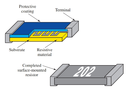
Figure 4. This cutaway drawing displays how a film resistor is constructed.
The substrate is made from glass, ceramic, or silicon, and it is used as an insulator base for the resistor. A layer of resistor material is deposited on the substrate in a zigzag pattern precisely engineered to produce the desired resistance value.
The resistor materials are made from metals or carbon mixed in a precise proprietary formula. The result is a thin film, which is only a few micrometers thick or thick film, which is 10 to 50 micrometers thick.
A protective coating is used to cover the resistor material deposited on the substrate. The ends of the film resistor serve as connection terminals and are made of metal such as nickel or silver, or they can be made from an alloy.
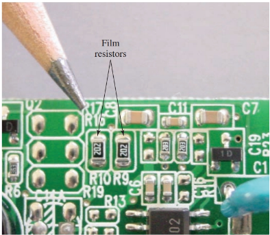
Solder is used to mount and connect the film resistor to the circuit board. See Figure 5.The process is very similar to the same process used to manufacture integrated circuits (ICs).
Figure 5. You can see film resistors mounted on a circuit board.
The number stenciled directly on surface-mounted resistors indicates the resistance value. When a three-digit number is used, the first two digits represent the first two digits of the resistance value and the third digit represents the number of zeros to add to the first two digits. For example, the 202 in Figure 5 represents the resistance value 2000 or 2k, + or – 5% tolerance (meaning it is allowed to vary by 5%).
When four digits are used, a tolerance of + or – 1% exists. For four-digit numbers, the same rule applies that the last digit represents the number of zeros. For example, 5002 would represent 50,000 or 50 k ohms, + or – 1% tolerance. For resistance values that require a decimal, the letter “R” is used to indicate the decimal point. For example, 7R5 would represent 7.5 ohms.
Film technology is not restricted to single resistors but may also be designed to produce resistor networks on a single chip. A resistor network consists of two or more independent resistors contained in one single surface- mounted package.
Wire Wound Resistor
For higher current uses, resistors are wire wound. A thin wire is wound on a ceramic core. The wire has a specific fixed-value resistance. The entire component is insulated by a coat of vitreous (opaque) enamel. These resistors are shown in Figure 6.
Wire wound resistors are commonly manufactured in sizes from 5 to 200 watts. The wattage chosen depends on the heat dissipation required during operation. Metal oxide resistors are also used for high voltage and wattage requirements.
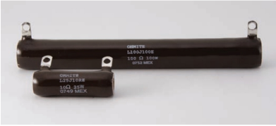
Figure 6. Wire wound resistors.
Adjustable Resistor
Another type of wire wound resistor is the adjustable resistor. Unlike the standard wire wound resistor, the adjustable resistor is not entirely covered by enamel material. Instead, a portion of one side of the wire is exposed.
An adjustable sliding tap is attached to move across the exposed surface. This allows the resistance value to be varied. Adjustable resistors may have two or more taps for providing various resistance values in the same circuit. An adjustable resistor and symbol are shown in Figure 7.
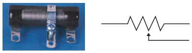
Figure 7. This adjustable resistor provides a sliding tap for voltage divider uses. On the right is the schematic symbol for an adjustable resistor.
Potentiometers
Most electronic equipment requires the use of variable resistance parts. A potentiometer is a very common type of variable resistor found in electronic projects. The potentiometer has a rotary knob that varies the resistance value as it is turned.
The variation in resistance is provided by a contact that is attached to a ring of resistive material inside the device. This device is similar to the wire wound resistor.
Many potentiometers are constructed with thin wire inside as the source of resistance. Various styles of potentiometers are illustrated in Figure 7a. Also shown is the potentiometer’s schematic symbol.
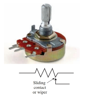
Figure 7a. Potentiometers are used in electronic circuitry for fixed and variable resistance. Notice that the schematic symbol for the potentiometer is the same as for the adjustable resistor.
Thermistors
A special type of resistor is called a thermistor. In comparison to other types of resistors, the thermistor is unusual due to its ability to change resistance value rapidly as its temperature changes. It is commonly used to prevent high inrush currents in electrical circuits.
An example of a thermistor use can be seen in a blow dryer. A common blow dryer has heating elements composed of tungsten wire. The tungsten wire has a very low resistance value when cold, and a high resistance value when red hot. The thermistor is placed in series with the heating elements to prevent a high current value when the dryer is first turned on. As the blow dryer heats up, the resistance value goes down. The result is a fairly consistent current value as the dryer’s heating element changes from low resistance (cold) to high resistance (hot).
Early blow dryer models caused a dimming and flickering of lights and other electronic equipment in the home because of inconsistent current draw. The thermistor eliminates this problem.
Resistor Color Code
Larger resistors are usually marked with their numerical resistance value printed directly on the side of the resistor. However, this type of labeling is not always practical, especially on small resistors. The resistor color code system was developed for this purpose.
The color code marking system has been adopted by the Electronics Industries Association (EIA) and the United States Armed Forces. This system of color coding is recognized throughout the world. Refer to Figure 8. Note how the color codes are printed, or banded, around the entire body of the resistor. This method of coding permits the value of the resistor to be read regardless of the mounting position. To see how to read the color coded bands refer to Figure 9.
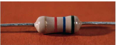
Figure 8. Color coded bands encircle the resistor.
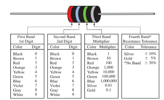
Figure 9. Standard color code for resistors.
Resistors commonly have three or four (and sometimes five) bands. Each band has a unique meaning.
- The first band represents the value of the first digit of the resistance value.
- The second band represents the second digit of the resistance value.
- The third band is called the multiplier. The multiplier gives the factor of ten that the first two digits should be multiplied by.
- The fourth band represents the tolerance of the resistor.
Resistor tolerance is a reflection of the precision of resistor’s value. If a 20 ohm resistor has a 10% tolerance, the resistor’s value can vary by ± 2 ohms. In this case the resistor can have a true resistance value of 18 to 22 ohms. A fifth band is sometimes used to indicate resistor reliability or expected failure rate.
See Figure 10. In the first sketch, the first bar is red and the second bar is violet. Checking the color code chart shows the first two digits in the resistor’s value to be 2 and 7 (or 27). This number is then multiplied by the third band. The third band is brown (× 10). This indicates that the value 27 is multiplied by 10, for a final value of 270 ohms. This is what the resistor value would be if the resistor was perfect. However, the fourth band is silver. This indicates that this resistor has a tolerance of 10 percent. In this example, the tolerance is a ±27 ohms (270 × 0.1 = 27). Thus the value of this resistor is somewhere between 243 ohms and 297 ohms.
Work out the stated value, maximum value, and minimum value for the other two sketches in Figure 10 on your own.
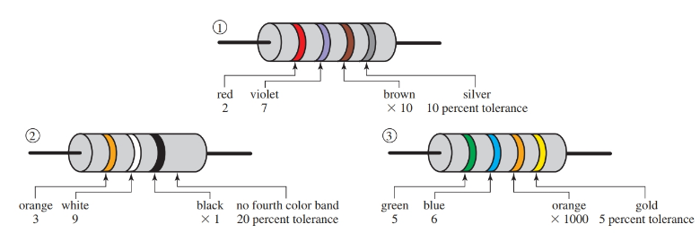
Figure 10. Examples of standard color-coded resistors.
Resistor Types and Color Code Key Takeaways
The various types of resistors, including carbon composition, thin and thick film, wire wound, adjustable resistors, potentiometers, and thermistors, play vital roles in a wide range of electronic applications. These components are essential for controlling and regulating the flow of electrical current, ensuring circuits function efficiently and safely. For instance, potentiometers and adjustable resistors are commonly used in applications requiring variable resistance, such as in volume controls and dimmer switches, while thermistors are crucial in preventing high inrush currents in devices like blow dryers. Understanding the different resistor types and their specific applications is fundamental for designing and troubleshooting electronic systems.