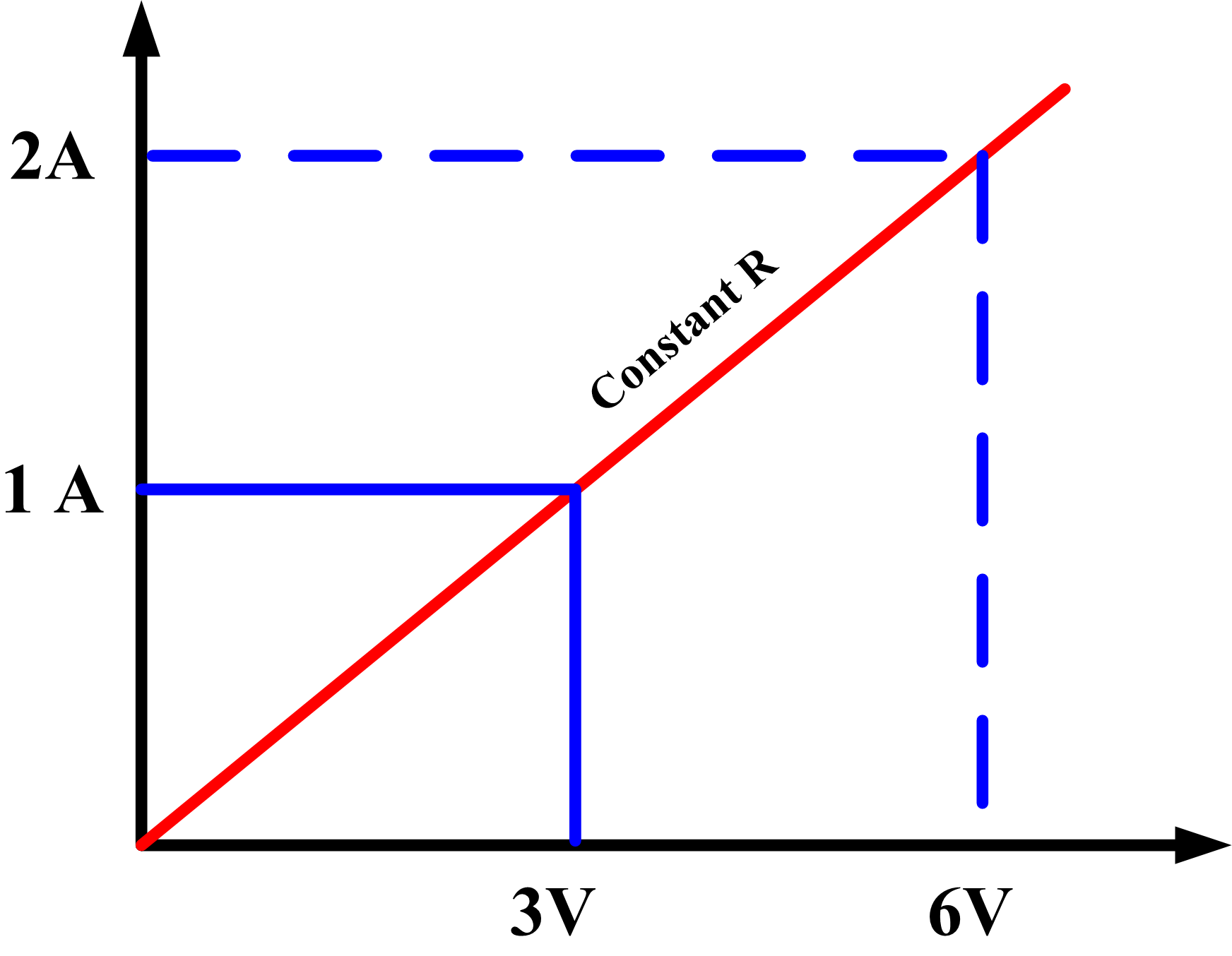
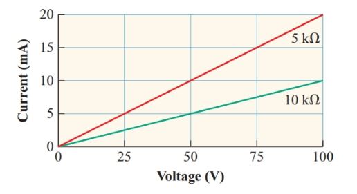
For most conductors, a graph of current versus voltage is a straight line, indicating a constant resistance (see Figure 1). The smaller the resistance, the steeper the slope of the graph.
Definition: A resistor that maintains a constant V/I ratio is a linear resistor.
As the current through a resistor increases, more heat is produced in the resistor, raising its temperature. This increase in temperature causes a slight increase in the resistance of most conductor materials.
For the common conductor materials such as copper and aluminum, the change in resistance over the ranges of operating temperatures for most circuits is so small that these materials are usually considered to be linear resistors.
Figure 1 Current versus voltage Characteristic curve for linear resistors
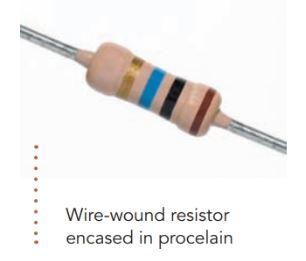
As the name suggests, wire-wound resistors have a metal wire wound on a hollow porcelain tube and sealed in position with a porcelain coating. These resistors are usually made with constantan or other alloys with a temperature coefficient of almost zero.
The larger the size of a resistor, the more readily it can dissipate heat to the surrounding air, and hence the greater the power rating.
Inexpensive, mass-manufactured resistors often have resistances that vary by 10% or more from their nominal values.
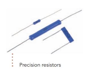
While such resistors are adequate for many types of circuits, applications such as measuring instruments require resistors that are accurate to within 1% or less of the nominal resistance. Such precision resistors are often made by depositing a thin film of metal or carbon on a small ceramic cylinder, to which leads are attached.
The film may be etched to adjust the resistance to the specified value before being coated with a layer of insulating material.
Resistors used in electronic devices usually have resistances greater than kilohms (a thousand ohms) and pass currents of only a few milliamperes.
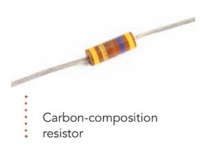
A carbon-composition resistor is commonly used when the current through the resistor produces less than 2 W of heat. The resistance element consists of finely ground carbon mixed with an insulating binder such as phenolic and pressed into a cylindrical shape with a wire lead embedded in each end. The resistance element is then sealed in a plastic jacket.
The length and width of the cylinder, the proportion of carbon in the mixture, and the way the mixture is compressed to determine the resistance.
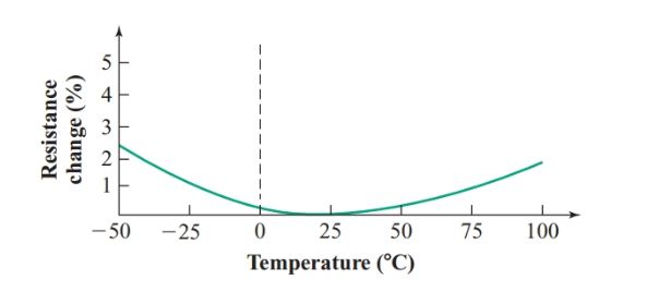
Carbon-composition resistors are much cheaper than wire-wound and film resistors, but the resistance of a carbon-composition resistor increases if the temperature varies appreciably from 20°C as shown in Figure 2.
For moderate temperature variations, the resistance changes by only a few percents, so we can usually treat carbon-composition resistors as linear resistors.
Figure 2 Resistance-temperature characteristic curve of carbon-composition resistors
Composition resistors are also made with a ceramic consisting of tin oxide and antimony bound with glass. Ceramic-composition resistors are particularly useful for circuits where the resistors must withstand voltage or energy surges.
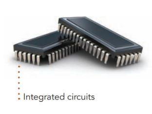
Integrated circuits (ICs) range from simple resistor networks to microprocessors containing millions of microscopic resistors and transistors. ICs start as a wafer of highly purified silicon.
Pure silicon is a poor conductor since it has few free charge carriers. The resistors are made by diffusing tiny regions of the silicon with precisely controlled amounts of elements that supply free electrons, making the regions more conductive.
Nonlinear Resistors
Definition: The property exhibited by devices whose resistance does not change uniformly with changes in voltage or current.
Incandescent Lamp
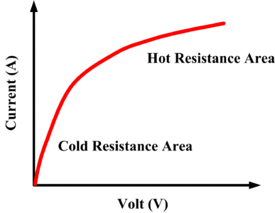
When an incandescent lamp is switched on, the temperature and the resistance of its tungsten filament increase dramatically.
When white-hot, the filament of an ordinary 60-watt 120-V lamp has a resistance of 240 Ω, but its resistance at room temperature is about 18 Ω.
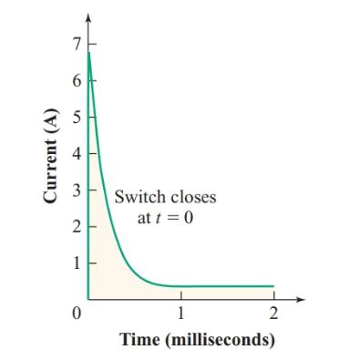
An incandescent lamp is a nonlinear resistor. The inrush current at the instant the lamp is turned on is much greater than its normal operating current:
$\begin{align} & Normal\text{ }I=\frac{V}{R}=\frac{120V}{240\Omega }=0.5A \\ & Inrush\text{ }I=\frac{V}{R}=\frac{120V}{18\Omega }=6.6A \\\end{align}$
Fortunately, the mass of the lamp filament is small enough that it gets white hot in less than a millisecond. Therefore, the current surge is brief, as shown in Figure 3.
Nevertheless, switches used with incandescent lamps have to be designed to withstand the inrush current. To avoid large inrush currents, heating elements, such as those in stoves, are usually made from an alloy with a very small temperature coefficient.
Figure 3 Inrush current of a 60-W incandescent lamp
The curve in figure 4 shows how the resistance changes with voltage for an incandescent lamp.
Figure 4: Incandescent Lamp Voltage-Current Characteristics Curve
Thermistor
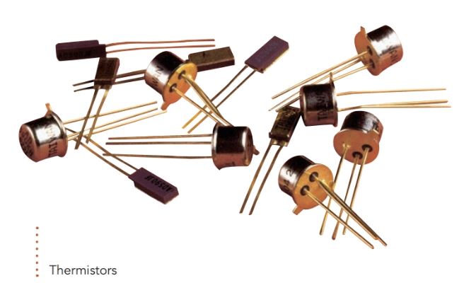
A resistor with a large negative temperature coefficient, called a thermistor, can be used to limit inrush currents.
Typically, such thermistors have a resistance of over 100 Ω at room temperature, but with a current of 1 A through them, their resistance drops to less than 1 Ω after 10 to 15 s.
These thermistors contain semi-conductive metal oxides with a ceramic binder. Heat produced by current through the resistor breaks covalent bonds in the metal oxides, creating enough free electrons to reduce the resistance to a fraction of its value at room temperature.
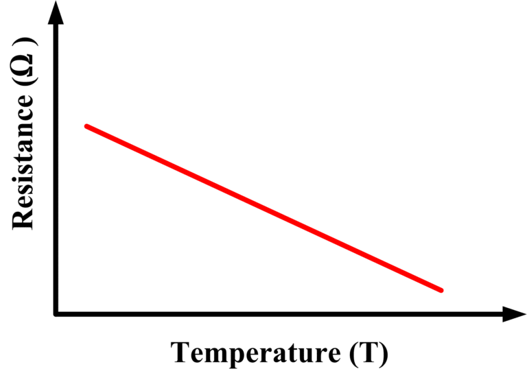
Small thermistors are used to measure temperatures since a decrease in temperature of less than 20°C will more than double their resistance.
Figure 5: Thermistor resistance-temperature Characteristic Curve
Varistor
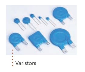
Varistors depend on the nonlinear resistance characteristic of zinc oxide or silicon carbide crystals, which are formed into wafers with a clay binder.
Zinc oxide Varistors (also called metal-oxide Varistors or MOVs) are used to protect sensitive electronics from voltage surges.
Silicon carbide Varistors (commonly known by the trade name thyrite) can protect high- voltage systems. They are used as lightning arrestors on power transmission lines.
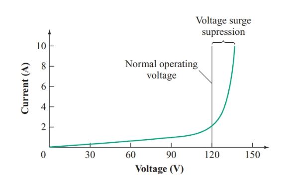
Temperature has little effect on the resistance of a varistor. Instead, a rapid increase in the number of charge carriers occurs when the potential difference across the varistor becomes greater than the threshold of the varistor. As Figure 6 indicates, the resulting decrease in resistance is such that the current through the varistor increases greatly without appreciably increasing the voltage drop across it.
Thus, a varistor connected across the power input to a device can protect it from voltage surges.
Figure 6 Typical varistor characteristic curve
Photo-Resistor
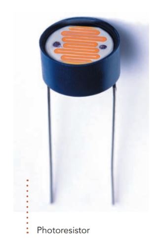
A photoresistor, photoconductor, or light dependent resistor (LDR) contains a thin zigzag strip of cadmium sulfide or cadmium selenide.
Light falling on the strip breaks down valence bonds in the cadmium compound, creating additional charge carriers.
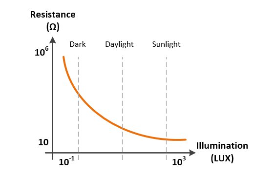
The resistance can range from hundreds of kilohms in the dark to less than 100 Ω in bright daylight. Photoresistors are widely used in light meters, auto-exposure circuits in cameras, and controllers for outdoor lights.
Figure 7: Photoresistor Characteristic Curve
Thermistors, Varistors, and photoresistors all use semiconductors engineered to become more conductive under specific conditions. The schematic symbols for these nonlinear resistors are shown in Table 1.
Table 1 Schematic symbols for nonlinear resistors
