The article provides an overview of clamp meter usage, highlighting its function in measuring current through magnetic fields without circuit interruption. It also outlines proper usage techniques and practical applications, such as safely identifying and isolating electrical circuits.
A clamp-on ammeter is a meter that measures the current in a circuit by measuring the strength of the magnetic field around a single conductor. Clamp-on ammeters measure currents from 0.01 A or less to 1000 A or more.
A clamp-on ammeter is normally used to measure current in a circuit with over 1 A of current and in applications in which current can be measured by easily placing the jaws of the ammeter around one of the conductors.
Most clamp-on ammeters can also measure voltage and resistance. To measure voltage and resistance, the clamp-on ammeter must include test leads and voltage and resistance modes. See Figure 1.

Figure 1. A clamp-on ammeter includes test leads and voltage and resistance modes.
Electricians must ensure that clamp-on ammeters do not pick up stray magnetic fields by separating conductors being tested as much as possible from other conductors during testing. If stray magnetic fields are possibly affecting a measurement, several measurements at different locations along the same conductor must be taken.
Clamp-On Ammeter Current Measurement.
AC or DC measurements using a clamp-on ammeter or a digital multimeter (DMM) with a clamp-on current probe accessory follow standard procedures. See Figure 2.
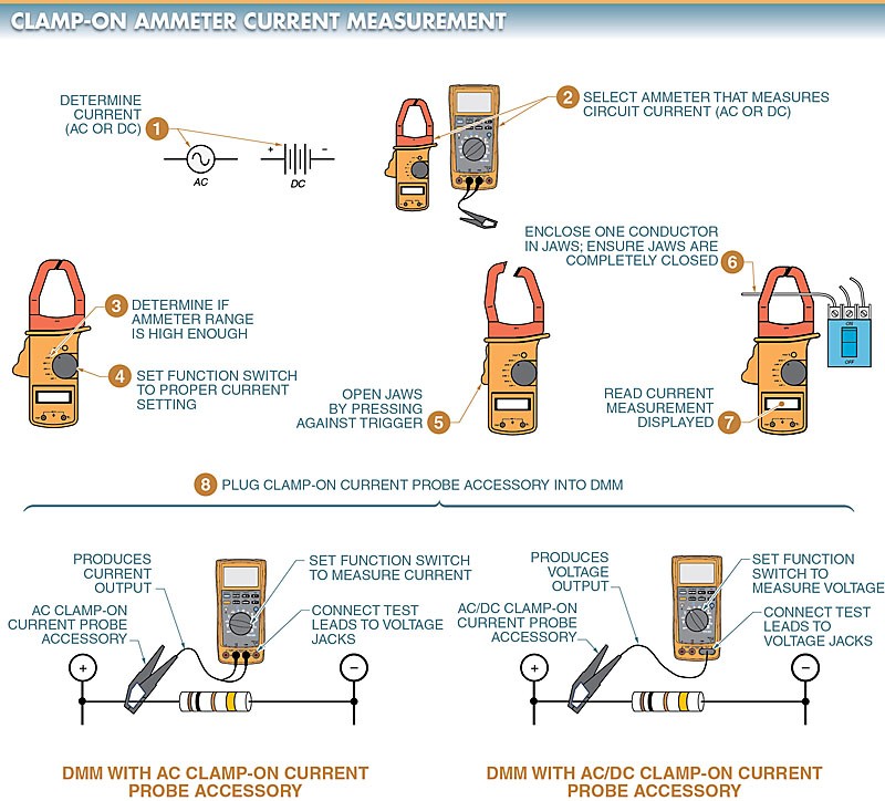
Figure 2. A clamp-on ammeter measures the current on a circuit by measuring the strength of the magnetic field around a single conductor.
How to Use a Clamp Meter to Measure Amps
To measure current using a clamp-on ammeter, the following procedure is applied:
- Determine if AC or DC current is to be measured.
- Select the ammeter required to measure the circuit current (AC or DC). If both AC and DC measurements are required, select an ammeter that can measure both AC and DC.
- Determine if the ammeter range is high enough to measure the maximum current that may exist in the test circuit. If the ammeter range is not high enough, select an accessory that has a high enough current rating, or select an ammeter with a higher range. If the ammeter includes fused current terminals, check to ensure that the ammeter fuses are good.
- Set the function switch to the proper current set- ting (600 A, 200 A, 10 A, 400 mA, etc.). If there is more than one current position or if the circuit current is unknown, select a setting greater than the highest possible circuit current.
- Open the jaws by pressing against the trigger.
- Enclose one conductor in the jaws. Ensure that the jaws are completely closed before taking readings. Care should be taken to ensure that the meter does not pick up stray magnetic fields. Whenever possible, conductors under test should be separated from other surrounding conductors by a few inches. If this is not possible, several readings should be taken at different locations along the same conductor.
- Read the current measurement displayed.
- If required, plug the clamp-on current probe accessory into the DMM. The black test lead of the clamp-on current probe accessory is plugged into the common jack. The red test lead is plugged into the mA jack for current measurement accessories that produce a current output. The red test lead is plugged into the voltage (V) jack for current measurement accessories that produce a voltage output. The current measurement accessories that produce a current output are designed to measure AC only and deliver 1 mA to the DMM for every 1 A of measured current (1 mA/A). Current accessories that produce a voltage output are designed to measure AC or DC and deliver 1 mV to the DMM for every 1 A of measured current (1 mV/A).
Locating Branch Circuits Using Clamp-On Ammeters.
A technician must often locate one circuit in a switchboard, panelboard, or load center to turn off the power before troubleshooting or working on a circuit.
Switchboards, panelboards, and load centers are often crowded with wires that are not marked or that are mismarked. A technician cannot start turning off each circuit until the correct circuit is found because this disconnects all loads connected to that circuit.
Timers, counters, clocks, starters, and other control devices must be reset, otherwise critical equipment such as alarms and safety circuits may be stopped. A flashing lamp and a clamp-on ammeter may be used to isolate a particular circuit. See Figure 3.
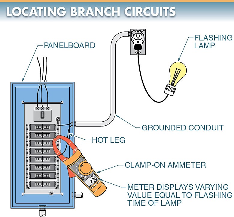
Figure 3. A flashing lamp and a clamp-on ammeter may be used to isolate a particular circuit
Tech Fact
Today, clamp-on ammeters are available that are capable of measuring currents as low as 4 mA and as high as thousands of amps. In addition, clamp-on ammeters are available with removable display heads for remote monitoring, flexible cables that open to enable connection around large conductors and bus bars, and small jaws with an attached lead that can be detached from the meter body and connected easily in tight areas.
The flashing lamp is plugged into any receptacle on the circuit that is to be disconnected. As the lamp flashes, a clamp-on ammeter is used to check each circuit. Each circuit displays a constant current reading except the one with the flashing lamp. The circuit with the flashing lamp displays a varying value on the ammeter equal to the flashing time of the lamp. This circuit may then be turned off for troubleshooting.
Clamp Meter Working Key Takeaways
Clamp meter are essential tools for electricians and technicians due to their ability to safely and efficiently measure current without disconnecting circuits. Their versatility in measuring AC/DC current, voltage, and resistance, along with their usefulness in isolating specific circuits in complex panels, makes them invaluable for troubleshooting, maintenance, and ensuring operational safety in a wide range of electrical applications.