In this section, single-phase transformers are reviewed with additional information; however, the main focus of the coverage here is the three-phase transformer. Three-phase transformers are used in large utility-scale renewable energy systems.
Single-Phase Transformer Basics
Recall that transformers act as a passive component in which two or more magnetically coupled coils are wound in a single core. The primary application is to convert ac from one voltage to another in both electronic and power circuits (although there are a few other applications).
Tapped, single-phase transformers are widely used in residential areas to step down the grid voltage to the requirements for household use. (In North America, this is 120 V/240 V.) Important equations relating the input and output voltage in a transformer were given in Equation as:
\[n=\frac{{{N}_{\sec }}}{{{N}_{pri}}}=\frac{{{V}_{\sec }}}{{{V}_{pri}}}\]
Where n is the turns ratio, Nsec is the number of turns in the secondary winding, and Npri is the number of turns in the primary.
This definition is one given by the Institute for Electrical and Electronics Engineers (IEEE) for electronics power transformers, but other definitions are based on a different category of transformer (such as an instrument transformer) that use turn ratio (singular); these transformers use the ratio of the higher-voltage winding to that of the lower-voltage winding.
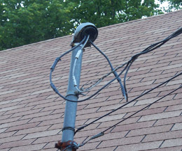
Figure 1: Single Phase Lines to a Residence
Electrical power from a single-phase transformer is connected to homes through a weather head.
Single-phase voltage is supplied by two hot wires and neutral (in the United States) that is provided by a very strong steel wire that is wrapped around the insulated wires to provide support.
The steel wire is connected securely to the mast on the roof and at the transformer to minimize the droop when they are run overhead.
The wires at the bottom of the mast in this photograph are telephone and cable television lines.
Another useful relationship for single-phase transformers is introduced here. No device is 100% efficient, and transformers are no exception.
Power transformers, which are designed for a single frequency, are very efficient and, in general, you can assume they are 100% efficient (or ideal) for basic calculations. Given this assumption, the power delivered to the primary is equal to the power delivered to the load, and no power is lost internally in the transformer; that is:
\[{{P}_{pri}}={{P}_{sec}}\]
Ppri = power delivered to the primary, in W
Psec = power delivered to the load, in W
This simplified equation does not consider transformer heating; however, it is useful for many basic transformer calculations. By substitution, it is evident that, in an ideal transformer ${{N}_{pri}}{{I}_{pri}}={{N}_{\sec }}{{I}_{\sec }}$ , Rearranging:
\[\frac{{{V}_{\sec }}}{{{V}_{pri}}}=\frac{{{I}_{pri}}}{{{I}_{\sec }}}\]
This is just another way to write the turns ratio as defined previously.
Notice that for a step-down transformer, voltage is stepped down, but the current is stepped up by the same amount.
Likewise in a step-up transformer, voltage is stepped up, but the current is stepped down by the same amount. Keep this in mind when you are selecting a fuse for a transformer circuit or calculating power delivered to a load.
Because ac circuits have phase shifts, the power rating on a transformer is not generally shown in watts but instead in volt-amperes (VA).
The volt-ampere (VA) rating is the maximum allowed apparent power dissipated for a device and is found by multiplying the voltage (volts) by the current (amperes).
The reason VA is used rather than watts is that the product of voltage and current can be higher if there is a reactive load, and the VA rating rather than wattage rating is what determines the safe operating limit.
Selecting a Single-Phase Transformer
If you are connecting a piece of equipment to a new transformer or if you are selecting a transformer for a renewable energy system, you need to size the transformer correctly so it does not overheat.
A transformer that is too small will overheat. One that is too large will cost more than necessary.
- Start by determining the required load voltage and load current. For most devices, you can obtain this information from a nameplate (data plate) on the device.
- Next, calculate the VA (or kVA) by multiplying the load voltage times the load current (or read it from the nameplate).
- In most cases, the nameplate shows the required frequency as well, which should be the same as the frequency of the source voltage.
- Verify that the load requires single-phase voltage. If a nameplate is not available, you can generally get the specifications from a user manual or the manufacturer.
- At this point, you can select a transformer with a standard kVA capacity that is equal to or greater than the load requirement.
- Transformer specifications are normally listed by kVA rating and either turns ratio or the input/output voltage ratings.
- Depending on the transformer, you may need to select the correct voltages on the primary and secondary side by connecting the source and load to one of several taps on the transformer.
Three-Phase Transformer Working
Three-phase transformers can be integrated as one unit or they can consist of three individual single-phase transformers that are wired together to operate in a three-phase system.
Figure 2 shows a cutaway view of a three-phase transformer wound on a single iron core. When the three windings are on a single core, the transformer can be manufactured at a lower cost as a single unit.
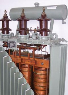
Figure 2 Cutaway View of a Three-Phase Transformer
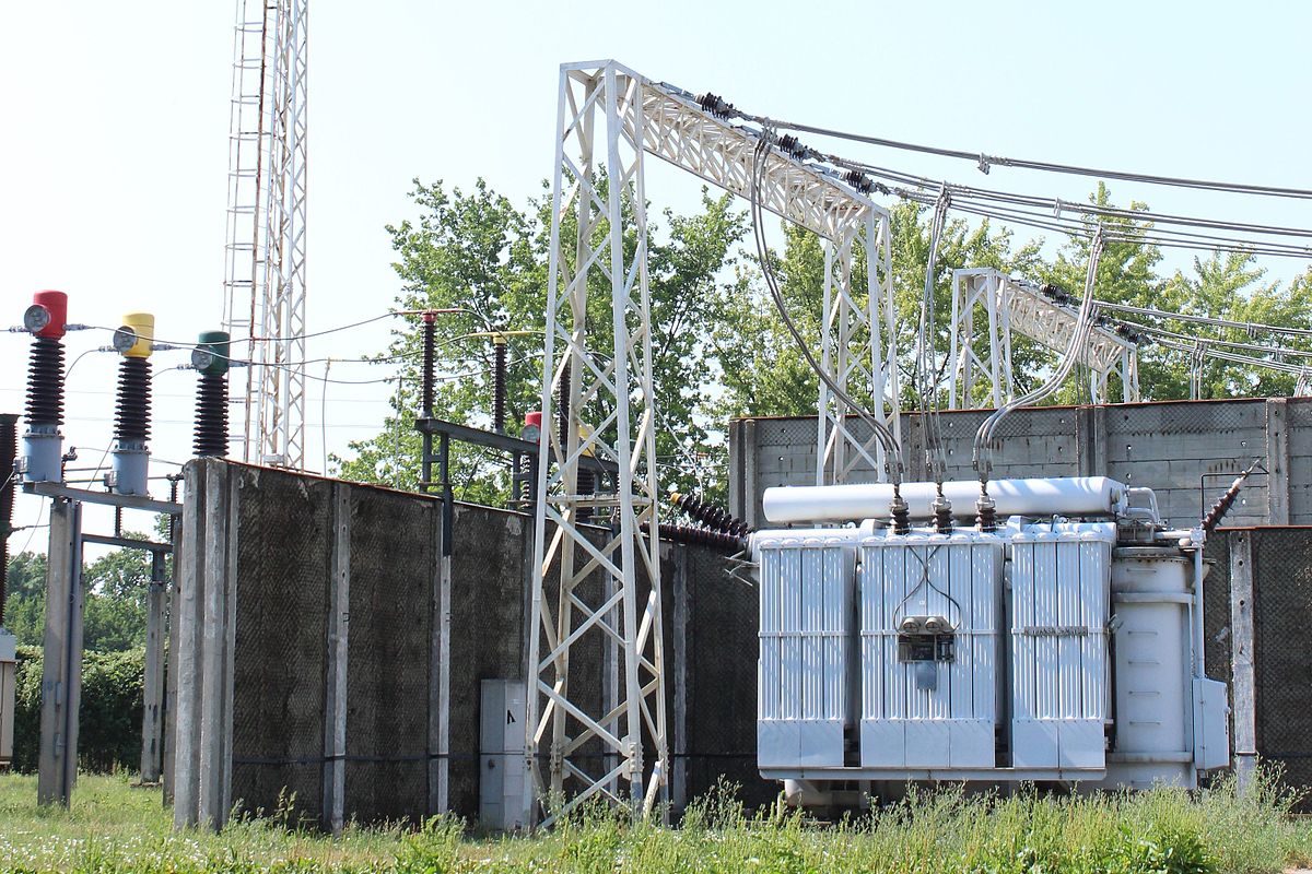
Figure 3a shows the transformers in the yard of a coal-fired power station that is in the process of converting to co-generation with biofuel.
Notice that this plant uses groups of three single-phase transformers to step up the voltage for transmission. This simplifies replacement if one transformer goes out.
Large transformers like this can get hot under load. Three separate transformers can be cooled easier than a single one can, and they can better handle overloads when they occur.
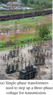
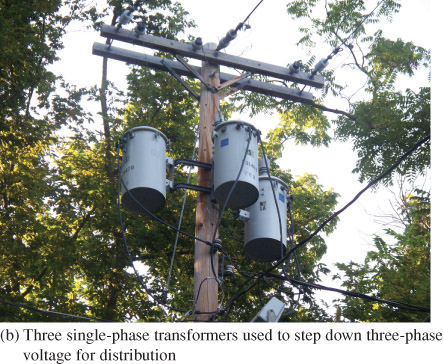
Figure 3 Single-Phase Transformers Used in Three-Phase Systems
Figure 3b shows a utility pole with three single-phase transformers to transform three-phase at the distribution end.
The main advantage to using three individual transformers, in this case, is that one or two of the transformers can be larger than the other(s) if the load is unbalanced.
Also, the weight is distributed to the three individual transformers, which, in some cases, makes it easier to handle.
If a failure occurs in one, the replacement is simplified because only the one with the failure needs to be replaced.
Otherwise, the three individual single-phase transformers operate exactly like the integrated three-phase transformers. The choice about which to use depends on the application.
Transformers can be designed for outdoor use by making the enclosure waterproof so that rain or snow does not get into the electrical connections.
Some transformers are specifically designed for indoor use and their enclosure is not watertight.
Some transformers in larger buildings are located in a special room called a transformer vault, which allows the transformers to be inspected from time to time.
Windings on a Three-Phase Transformer
Figure 4 shows a three-phase transformer that has three separate primary and three secondary windings wound on a common core.
The primary winding of each transformer phase is mounted close to its secondary winding for effective coupling of the primary voltage to the secondary winding.
The three primary windings are identical to each other, and the three secondary windings are identical to each other. The leads for all six of the windings are available externally.
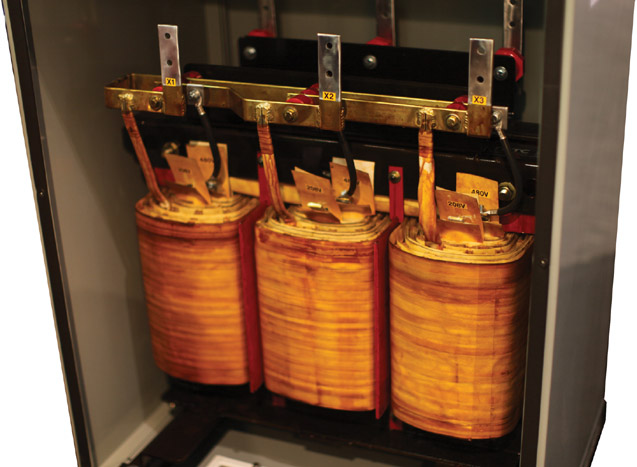
Figure 4 Three-Phase Transformer. The windings are on a common core and are separated by insulators.
Three Phase Transformer Connections
The three primary and three secondary windings are available externally for connecting in either of two common configurations: a delta (Δ) or a wye (Y).
Figure 5a shows the primary winding connected in a delta and the secondary connected in a wye configuration. Figure 5b shows the same schematic drawn so that is similar to what you see as a physical installation.
Some three-phase transformers may use other terminal identification numbers or letters, but the connections are equivalent.
One common naming convention is to label the high-voltage windings with the letter H and the low-voltage windings with the letter X (neutral is X0).
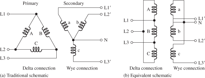
Figure 5 Delta-Wye Connected (Δ-Y) Transformer. The circuits in parts (a) and (b) are identical.
When all leads are brought out, a three-phase transformer can be connected in any of four combinations: Δ-Y, Y-Δ, Δ-Δ, or Y-Y, although only the first three are generally used.
The first three combinations have certain advantages and disadvantages. For example, the wye connection has a central connection point from which neutral can be brought out.
A variation on a standard delta connection is making a center-tap from one of the windings available on a delta secondary. This configuration to illustrate a method for splitting a phase, which is the norm in residential homes in North America. In this case, the center-tap is the neutral winding.
When connecting a delta, it is important to check for proper polarity before applying power because an incorrect configuration can lead to extremely high current.
You saw how a delta connected secondary can be used to provide single-phase voltage.
Single-phase voltage can also be obtained from a wye connected transformer. The wye connected transformer can provide 208 V, which is used in some commercial and industrial locations but rarely in residential locations, where loads require 240 V.
Instead of a center-tap on one of the coils, the center-tap for the neutral connection is exactly in the midpoint where the three windings are joined; that midpoint is called the Wye point. Anyone of the three lines can be used for a single-phase supply when combined with neutral.
In industrial and commercial applications, wye connected transformers with 480 V line to line provide 277 V line to neutral, and this voltage is used to power fluorescent lighting.
Important points about the configurations of three-phase transformers are discussed in the next subsections.
Delta-Wye Transformer Connection
The delta-wye connected transformer has a delta connection on the primary side and a wye connection on the secondary side.
In Europe, this type of connection is called a delta-star transformer. The delta-wye is one of the most widely used connections. It can be configured as either a step-up or step-down transformer.
The neutral can be brought out from the secondary side where the three windings are joined so that a single-phase voltage is available for lighting or electrical outlets in an office.
The secondary side of the delta-wye transformer must be grounded at the wye point according to the National Electrical Code (in the United States) as protection against shorts.
When the delta-wye transformer is used as a step-up transformer, the wires on the secondary side that provide high voltage are smaller because of the lower current. This feature makes this type of transformer very useful for renewable energy systems because it can step up the voltage for transmission over long distances.
Wye-Delta Transformer Connection
The wye-delta three-phase connected transformer is most commonly used in a step-down transformer application.
The wye connection on the high-voltage primary side provides a place for a ground to be connected at the wye point.
The wye connection on the high-voltage side reduces insulation costs. It has the advantage of being stable when driving unbalanced loads.
Delta-Delta Transformer Connection
The delta-delta connection is useful when three single-phase transformers are connected as a three-phase transformer.
An advantage of this configuration is that if one of the transformers fails, it can be replaced while the other two continue to operate and supply power at a reduced level (this is called an open delta).
The delta-delta connection can be used as a step-up or a step-down transformer. This type of connection is required by National Electrical Code (NEC) to be grounded on its secondary windings or to have ground fault protection in each phase in the secondary winding.
Wye-Wye Transformer Connection
The wye-wye connection is rarely used. It has problems with unbalanced loads, which can cause overheating.
Tapped Transformers
In large distribution transformers, it is common for the primary or secondary to have tapped terminals.
Taps near the end of a winding enable fine adjustment of the voltage at the site so that it matches the load requirements more closely. The reason it is necessary to adjust at the site is that voltages from utilities are not the same in all locations due to different drops along the distribution path.
Taps are used to adjust consistently high or low voltages, not for normal fluctuations.
Taps are also used as a center-tap. Center-tapped transformers with the tap on the secondary are widely used in electronic applications.
They are also used in three-phase systems, as was previously illustrated with the three-phase to the single, split-phase transformer.
Phase and Line Voltages and Currents
Voltages and currents are typically described in three-phase systems as either phase voltages and phase currents or line voltages and line currents.
The phase voltage or current refers to the components in the wye or delta. Thus, a phase voltage is across one of the coils, and a phase current is a current in the coil.
The line voltage or current refers to the connections to L1, L2, and L3; thus, a line voltage is between two of the external lines.
Notice that the line voltage is equal to the phase voltage for a delta connection because both are measured across the same two points.
Likewise, the line current is equal to the phase current for a wye connection because the current is in the same wire.
Figure 6 illustrates representative line and phase voltages and currents for the delta and wye configurations.
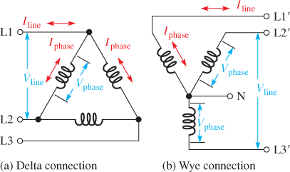
Figure 6 Representative Phase and Line Voltages and Currents. In the delta connection, Vline = Vphase and Iline > Iphase. In the wye connection, Iline = Iphase and Vline > Vphase.
In a delta connected winding that has a balanced load, the line current splits into two phase currents.
The phase currents are not one-half of the line current because of the phase angle differences. Rather, they are related by a factor of √3. The equation for phase current in a delta connection with a balanced load is:
$\begin{matrix} {{\mathbf{I}}_{\mathbf{PHASE}}}~=~{{\mathbf{I}}_{\mathbf{LINE}}}~\div ~\sqrt{3} & {} & \left( 1 \right) \\\end{matrix}$
Likewise, for a balanced wye connection, the phase voltage is related to the line voltage by this same factor of √3 Thus, the equation for phase voltage in a wye connection with a balanced load is:
$\begin{matrix} {{\mathbf{V}}_{\mathbf{PHASE}}}~=~{{\mathbf{V}}_{\mathbf{LINE}~}}\div ~\sqrt{3} & {} & \left( 2 \right) \\\end{matrix}$
Example 1:
Draw a phasor diagram for a wye connected secondary with a 120 V phase voltage. Use it to show that the line voltage is 208 V by finding the difference in voltage between L1 and L3. This configuration is used in some industrial installations that require 208 V.
Solution:
The phase voltages (L, L2, and L3) are shifted by 120° from each other as shown in Figure 7a. Figure 7b shows the phasor diagram for L1 (blue) and L3 (green).
To find the difference between L1 and L3, reverse the direction of L3 as shown in Figure 7 (b), creating the phasor −L3. Add the inverted phasor (−L3) to L1 to find the difference (L1 − L3). You can find the length of L1 − L3 graphically or with basic trigonometry. From this, you can show that the difference is √3 × 120 V = 208 V.
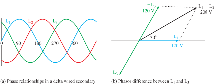
Figure 7 Graphical Solution to Example 1
Example 2:
A delta connected secondary has 480 V to a 100 Ω balanced load, as shown in Figure 8. Calculate the line and phase currents in the load, and the total power delivered to the load.
The load is typically a motor in a three-phase system, but to simplify the problem, resistors are shown. Assume the PF is 1.
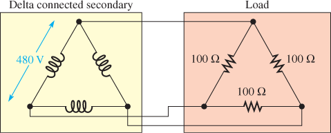
Figure 8 Delta Connected Secondary and Load
Solution:
The line voltage and phase voltages across the secondary and the load are the same and are equal to 480 V because of the parallel connections. The phase current in the load can be found by Ohm’s law:
Iphase=Vphase÷Rload=480 V÷100 Ω=4.80 A
As given in Equation 1, the line current is larger than the phase current in a delta by √3 thus:
Iline=√3 (4.80 A) =8.31 A
The power in each resistor is the phase voltage multiplied by the phase current. There are three resistors, so the total power is:
Ptotal=3×Vphase×Iphase=3× (480 V) × (4.80 A) =6.91 kW
A wye connected secondary and load has similar calculations. Because of phase relationships, the phase voltages rather than the phase currents include a factor of √3 in the calculation. The below example illustrates a wye connected secondary and load.
Example 3:
A wye connected secondary has 480 V, as shown in Figure 9, and is connected to a 75 Ω balanced load.
- Calculate the phase voltage across the load, the line and phase currents in the load, and the total power delivered to the load. As in Example 2, the load is assumed to be resistive for simplicity.
- Assume the connections are made using three single-phase transformers. What is the minimum VA rating of the transformers?
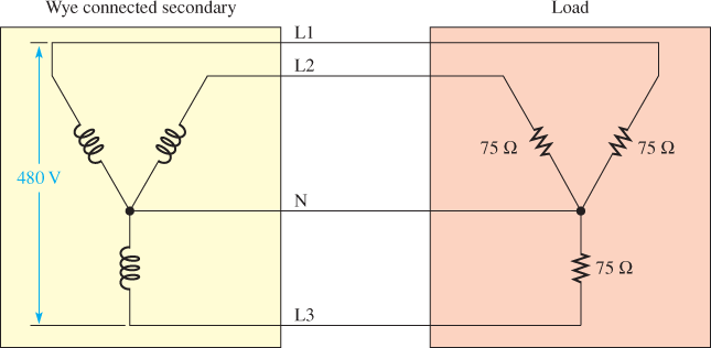
Figure 9 Wye Connected Secondary and Load
Solution
- The line voltage is given as 480 V. It is divided between two of the secondary coils. Because of the phase shift, the phase voltage at the source is given by Equation 2:
Vphase=Vline÷√3=480 ÷√3 =277 V
(This is the voltage from any line to N)
The phase voltage is identical in the load because of the parallel connection.
The phase current in the load can be found by Ohm’s law:
Iphase=Vphase ÷Rload=277 ÷75 Ω=3.70 A
The line current is the same in the wye connection because of the series connection.
Iline=3.70 A
The power in each resistor is the phase voltage multiplied by the phase current. There are three resistors, so the total power is:
Ptotal=3×Vphase×Iphase=3× (277 V) × (3.70 A) =3.07 kW
Each of the three transformers must be rated for one-third of the total, as long as the load is resistive (PF = 1, so kW = VA). Therefore:
3.07 kW÷3=1.03 kVA
(Note that the transformer is rated in VA, not W)
Troubleshooting a Transformer
Troubleshooting high-power transformers with voltages above 200 V requires special training and special personal protective equipment.
Personal protective equipment (PPE) consists of safety equipment such as safety glasses, safety shields, insulated gloves, hard hats, and suits to protect against arc flash for working on power systems with voltages above 200 V.
Larger voltages create an electrical hazard called arc flash (or arc blast), which is a high-current, high-energy arc between two points that have the potential to cause injury or death.
If you work for a company that does work on systems with the voltage above 200 V, you will be required to be trained in the procedures for working safely using the appropriate safety gear.
If the transformer you are testing is disconnected from power and there are no external paths for current (such as a load), you can test each of the windings with an ohmmeter for continuity.
Each of the coils should have some amount of resistance that indicates the amount of resistance in the wire in each coil.
A measure of infinite resistance (∞) indicates that the winding has an open; a measure of 0 ohms indicates that one of the windings is shorted.
Because transformers are basically coiling of wire, the ohmmeter should reveal a faulty transformer.
If the transformer passes the continuity test, you can apply power to its primary winding. If the transformer windings are not shorted or open, you can apply an ac voltage that is equal to or less than the primary voltage rating of the transformer and is able to measure the secondary voltage with no load.
If no voltage is present at the secondary, be sure to check all the connections to ensure that they are correct. A fault can be in the load, making it appear as if the transformer is the problem.
Review Questions
- What is the difference between a three-phase transformer and a single-phase transformer?
- What is the difference between a delta connection and a wye connection in a transformer?
- What is the difference between phase voltage and line voltage with reference to a transformer?
- What type of winding has a phase voltage equal to line voltage?
- What type of winding has phase current equal to line current?
Answers
- A single-phase transformer has one primary winding and one secondary winding. A three-phase transformer has three primary windings and three secondary windings.
- A delta connection has the three coils configured such that they could be arranged in the shape of the Greek letter delta (Δ), and a wye connection has the three coils configured such that they could be arranged in the shape of the letter Y.
- Phase voltage refers to the voltage across a component that is within the wye or delta configuration; line voltage refers to the voltage between the lines brought out of the transformer.
- A delta connection
- A wye connection
