The electrical industry has established a universal set of symbols and rules on how line diagrams (circuits) are laid out. By applying these standards, an electrician establishes a working practice with a language in common with all electricians.
One Load per Line
No more than one load should be placed in any circuit line between the power lines L1 and L2. For example, a pilot light can be connected to a circuit with a single-pole switch. See Figure 1. In this circuit, the power lines are drawn vertically on the sides of the drawing and marked L1 and L2. The space between L1 and L2 represents the voltage of the control circuit. This voltage appears across pilot light PL1 when switch S1 is closed. The pilot light glows when current flows through S1 and PL1 because the voltage between L1 and L2 is the proper voltage for the pilot light.
Two loads must not be connected in series in one line of a line diagram. If the two loads are connected in series, then the voltage between L1 and L2 must divide across both loads when S1 is closed. The result is that neither device receives the entire 120 V necessary for proper operation.
The load that has the highest resistance drops the highest voltage. The load that has the lowest resistance drops the lowest voltage.
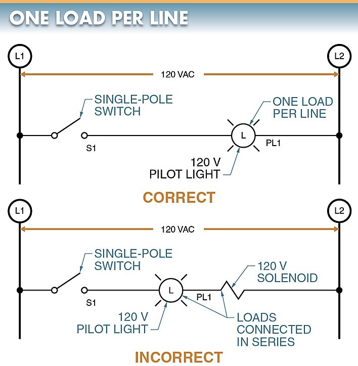
Figure 1. No more than one load should be placed in any circuit line between L1 and L2.
Loads must be connected in parallel when more than one load must be connected in the line diagram. See Figure 2. In this circuit, there is only one load for each line between L1 and L2, even though there are two loads in the circuit. The voltage from L1 and L2 appears across each load for the proper operation of the pilot light and solenoid. This circuit has two lines, one for the pilot light and one for the solenoid.
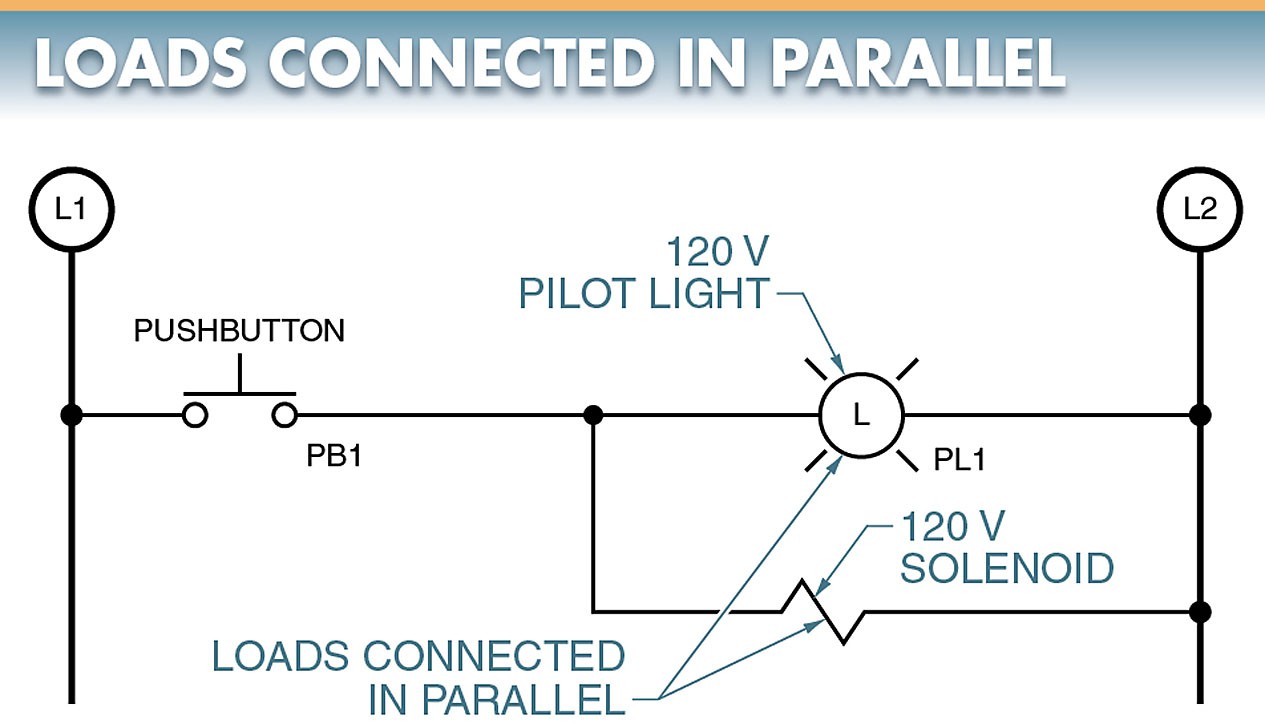
Figure 2. Loads must be connected in parallel when more than one load must be connected in the line diagram.
Load Connections
A load is any device that converts electrical energy to motion, heat, light, or sound. A load is an electrical device in a line diagram that uses the electrical power from L1 to L2. Control relay coils, solenoids, and pilot lights are loads that are connected directly or indirectly to L2. See Figure 3.

Figure 3. Control relay coils, solenoids, and pilot lights are loads that are connected directly or indirectly to L2.
Magnetic motor starter coils are connected to L2 indirectly through normally closed (NC) overload contacts. See Figure 4.
An overload contact is normally closed and opens only if an overload condition exists in the motor. The number of NC overload contacts between the starter coil and L2 depends on the type of starter and power used in the circuit.

Figure 4. Magnetic motor starter coils are connected to L2 indirectly through NC overload contacts.
One to three NC overload contacts may be shown between the starter and L2 in all line diagrams. One to three NC overload contacts are shown because starters may include one, two, or three overload contacts, depending on the manufacturer and motor used.
Early starters often included three overload contacts, one for each heater in the starter. Modern starters include only one overload contacts.
To avoid confusion, it is common practice to draw one set of NC overload contacts and mark these contacts all overloads (OLs). An overload marked this way indicates that the circuit is correct for any motor or starter used. The electrician knows to connect all the NC overload contacts that the starter is designed for in series if there is more than one on the starter.
Control Device Connections
Control devices are connected between L1 and the operating coil (or load). Operating coils of contactors and starters are activated by control devices such as pushbuttons, limit switches, and pressure switches. See Figure 5.
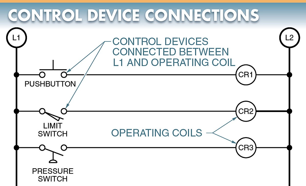
Figure 5. Control devices are connected between L1 and the operating coil.
Each line includes at least one control device. The operating coil is ON all the time if no control device is included in a line.
A circuit may contain as many control devices as are required to make the operating coil function as specified. These control devices may be connected in series or parallel when controlling an operating coil.
Although a circuit may include any number of loads, the total number of loads determines the required wire size and rating of the incoming power supply (typically a transformer). The total current increases as loads are added to the circuit.
Two control devices (a flow switch and a temperature switch) can be connected in series to control a coil in a magnetic motor starter. The flow switch and temperature switch must close to allow current to pass from L1, through the control device, the magnetic starter coil, and the overloads, to L2. See Figure 6.
Two control devices (a pressure switch and a footswitch) can be connected in parallel to control a coil in a magnetic motor starter. See Figure 6.
Either the pressure switch or the footswitch can be closed to allow current to pass from L1 through the control device, the magnetic starter coil, and the overloads to L2. Regardless of how the control devices are arranged in a circuit, they must be connected between L1 and the operating coil (or load).
The contacts of the control device may be either normally open (NO) or normally closed (NC). The contacts used and the way the control devices are connected into a circuit (series or parallel) determines the function of the circuit.
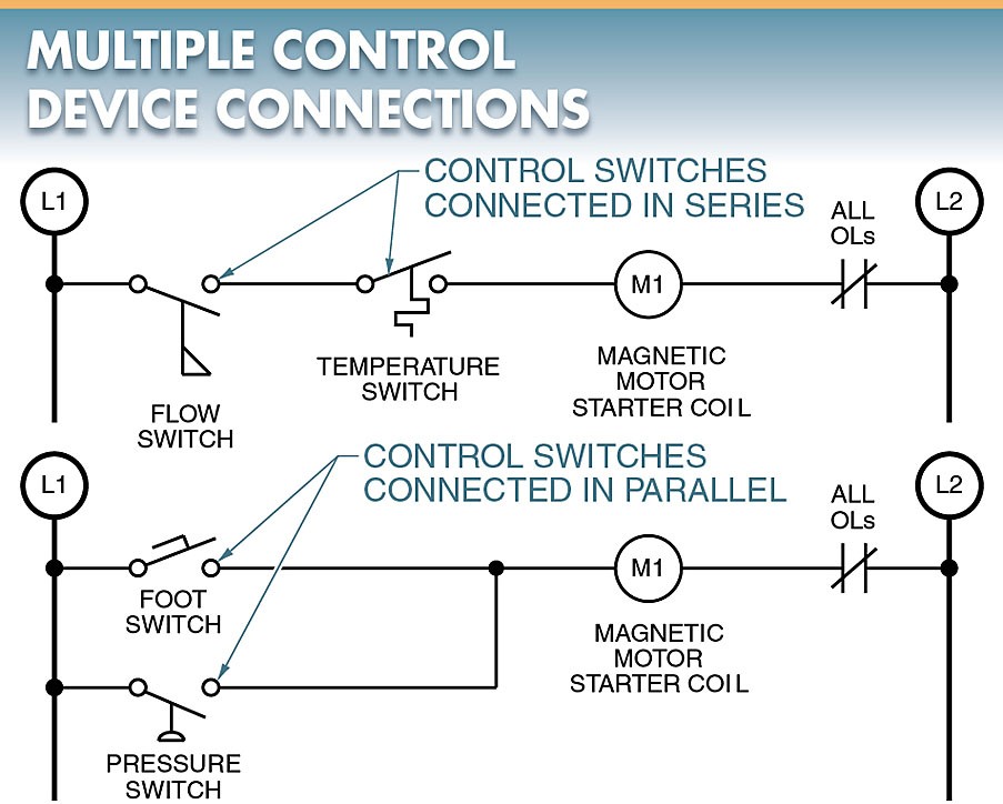
Figure 6. Two control devices can be connected in series or parallel to control a coil in a magnetic motor starter.
Line Number References
Each line in a line diagram should be numbered starting with the top line and reading down. See Figure 7.
Line 1 connects PB1 to the solenoid to complete the path from L1 to L2.
Line 2 connects PS1 to the solenoid to complete the path from L1 to L2. PB1 and PS1 are marked as two separate lines even though they control the same load because either the pushbutton or the pressure switch completes the path from L1 to L2.
Line 3 connects a footswitch and a temperature switch to complete the path from L1 to L2. The footswitch and temperature switch both appear in the same line because it takes both the footswitch and the temperature switch to complete the path to the pilot light.
Numbering each line simplifies the understanding of the function of a circuit. The importance of this numbering system becomes clear as circuits become more complex and lines are added.

Figure 7. Each line in a line diagram should be numbered starting with the top line and reading down.
