Electronic Overloads
New motor starters normally include an electronic overload instead of heaters. An electronic overload is a device that has built-in circuitry to sense changes in current and temperature.
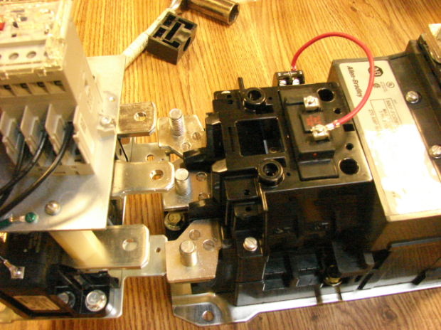
An electronic overload monitors the current in the load (motor, heating elements, etc.) directly by measuring the current in the power lines leading to the load. The electronic overload is built directly into the motor starter. See Figure 1.
An electronic overload measures the strength of the magnetic field around a wire instead of converting the current into heat. The higher the current in the wire leading to a motor, the stronger the magnetic field produced.
An electronic circuit is used to activate a disconnecting device that opens the starter power contacts. Electronic overloads have an adjustable range. The setting is based on the nameplate current listed on the motor.
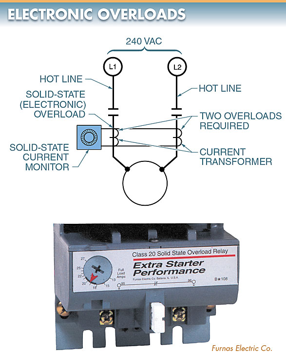
Figure 1. An electronic overload has built-in circuitry that senses changes in current and temperature.
Programmed Overloads
Magnetic motor starters protect motors from an overload by the addition of overload heaters to the starter. The motor nameplate current is used to select an overload size from a chart provided by the manufacturer of the magnetic motor starter.
An electronic overload protects a motor from an overload by the setting of an adjustment dial on the starter overload block to the motor nameplate current. When motor drives are used to control motors, motors are protected from an overload by programming the motor nameplate current into the drive.
On basic motor drives, motor overload protection is set with an adjustment dial on the motor drive. On advanced motor drives, motor overload protection is programmed into the motor drive using a keypad. See Figure 2.
When setting motor overload protection using the dial on a motor drive, the maximum rated continuous output current of the motor drive and the full-load current (nameplate current) of the motor is used to determine the dial setting. For example, if the maximum rated continuous output current of a motor drive is 10 A and the nameplate current of a motor is 10 A, the overload protection dial of the motor drive is set to 100%. See Figure 3.
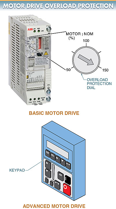
Figure 2 Motor overload protection may be programmed into a motor drive by setting a dial or using a keypad.
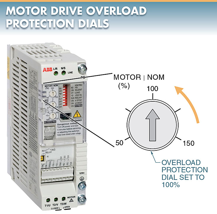
Figure 3. The overload protection dial is set to 100% if the maximum-rated continuous output current of the motor drive is equal to the full-load current (nameplate current) of the motor.
Motor nameplate current is the amount of current a motor draws when the motor is operating at its nameplate power (HP or kW) rating.
Normally, motors do not operate at 100% of their power rating. They also draw less current than the motor nameplate current. Motor drive current rating is the maximum continuous output current a motor drive can deliver for an extended period of time.
A motor drive can deliver more current than its maximum continuous output current rating for short periods of time. For this reason, the motor drive overload protection dial can be set higher than 100%. However, the overload protection should generally remain under 100%.
The high current produces more heat, which damages motor drives and motors. Motor current percentage is found by applying the following formula:
$\begin{align}& {{I}_{m}}\left( perentage \right)=\frac{{{I}_{mn}}}{{{I}_{mrd}}}\times 100 \\& where \\& {{I}_{m}}\left( percentage \right)\text{ }=\text{ }motor\text{ }current\text{ }percentage \\& {{I}_{mn}}\text{ }=\text{ }motor\text{ }nameplate\text{ }current\text{ }(in\text{ }A) \\& {{I}_{mrd}}=\text{ }maximum\text{ }rated\text{ }drive\text{ }current\text{ }(in\text{ }A) \\\end{align}$
When programming motor overload protection, motor nameplate current is programmed into a motor drive. On advanced motor drives, motor nameplate current is entered into the motor drive as a drive parameter using a keypad. The motor drive monitors current drawn by the motor and turns off the motor if there is an overload. See Figure 4.
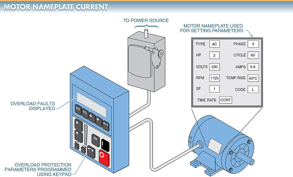
Figure 4. Advanced motor drives normally contain a keypad that is used to enter drive parameters, such as motor nameplate current.
Motor drives with advanced parameter programming may have customized overload protection for a given application. Some motor drives can be programmed to automatically attempt to restart a motor after an overload.
The number of automatic restarts permitted (normally no more than 9) and the amount of time (normally 1 sec to several minutes) between each automatic restart can be programmed.
AC Motor Drive Load Test
An AC motor drive load test is a test used to verify that a motor drive and motor function properly together to rotate a driven load. An AC motor drive set to factory defaults and controlled by an integral keypad is tested with a motor connected. At this point, inputs and outputs are not tested. See Figure 5.
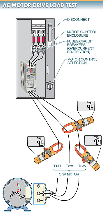
Figure 5. An AC motor drive load test is used to verify that a motor drive and motor function properly together to rotate a driven load.
To test an AC motor drive, motor, and load, the following procedure is applied:
- If the AC motor drive is ON, push the STOP button.
- Turn the disconnect off. Lockout/Tagout the disconnect.
- Wait for the DC bus capacitors to discharge. Do not manually discharge the capacitors. Remove the AC motor drive cover. Use a DMM to verify that the AC line voltage is not present. Use a DMM to verify that the DC bus capacitors have discharged. Do not rely on the DC bus and charge LED(s).
- Reconnect the load conductors to their previous locations on the power terminal strip in order to maintain correct motor rotation. Incorrect motor rotation causes damage in certain applications. Reinstall the AC motor drive cover.
- Remove the lockout/Tagout from the disconnect.
- Stand to the side of the disconnect and AC motor drive when energizing in case of a major failure. Turn on the disconnect. Do not push the START button. The AC motor drive LED display or clear text display should activate.
- Program the appropriate parameters into the AC motor drive with motor nameplate data.
- Program the display mode to show motor drive output frequency.
- For the safety of personnel and equipment, a technician should monitor and control the motor drive as another technician monitors the motor and load during the test. Do not start the motor drive until a check is made to ensure that personnel is not at risk from the load.
- Stand to the side of the disconnect and motor drive when energizing in case of a major drive failure. Push the START button. The LED display should ramp up to a low frequency. If the LED display shows 0 Hz, push the RAMP UP button until 5 Hz is displayed.
- Increase the frequency of the motor to 60 Hz using the RAMP UP button. The motor and load should accelerate smoothly to 60 Hz. Any unusual noises or vibrations must be recorded along with the frequency at which the occurrence appeared. Unusual noises or vibrations indicate alignment problems or require the use of the skip frequency parameter to avoid unwanted mechanical resonance.
- Remove the motor drive cover. CAUTION: Dangerous voltage levels exist when the motor drive cover is removed and the drive is energized. Exercise extreme caution and use the appropriate personal protective equipment.
- Measure and record the current in each of the three load conductors using a true-rms clamp-on ammeter. True-rms clamp-on ammeters are required because the current waveform of a motor drive is not a perfect sine wave. Current readings are taken at 60 Hz because the motor nameplate current is based on 60 Hz. Current readings of the three load conductors should be equal or very close to each other. A problem with the load conductors or motor is present if the current readings of the load conductors are not equal or very close to each other.
An overloaded motor is a motor that has a current reading greater than 105% of the nameplate current rating. There is a problem with the motor or the load if the current readings are greater than 105% of the nameplate current rating. Reinstall the motor drive cover.
- Decrease the speed of the motor to 0 Hz using the RAMP DOWN button. The motor and driven load must decelerate smoothly to 0 Hz. Any unusual noises or vibrations must be recorded along with the frequency at which the occurrence appeared. Unusual noises or vibrations indicate alignment problems or can require the use of the skip frequency parameter to avoid unwanted mechanical resonance.
- Push the STOP button.
- If the motor drive, motor, and load performed without any problems, the motor drive, motor, and load are not the source of the problem. The motor drive inputs should be tested.
- There is a problem if the motor drive, motor, and load did not perform correctly. The problem may be the motor drive parameters, motor, or load.
