Power is measured by means of an electrodynamometer instrument that has similarities to a PMMC instrument. In a DC Circuit, the power supplied to a load can be determined by measuring the load voltage and current and multiplying them together:
P=EI
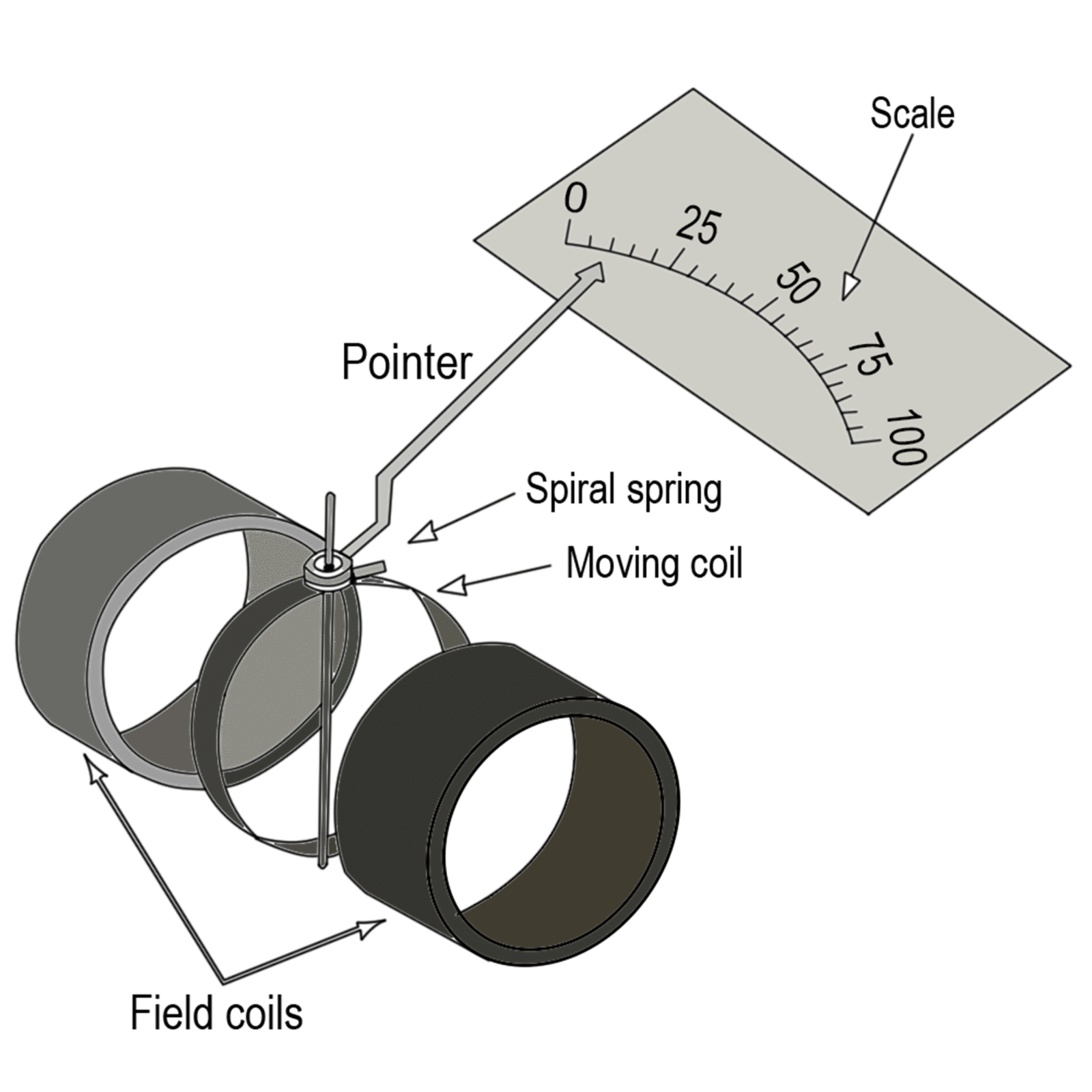
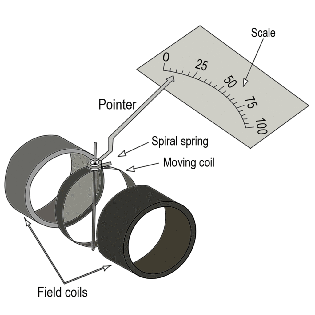
However, it is much more convenient to have an instrument that indicates power directly. The motor used for this purpose is called a wattmeter, and the instrument that can be applied as a wattmeter is known as a dynamometer, or sometimes as an electrodynamic instrument. The construction of a dynamometer instrument to some extent resembles the PMMC instrument. The major difference from the PMMC construction is that the permanent magnet is replaced by two coils, as illustrated in figure 1(a). The magnetic field in which the lightweight moving coil is situated is generated by passing current through the stationary field coils. Then, when a current is passed through the moving coil, the moving coil and the meter pointer are deflected.
Fig. 1(a): Basic construction of a dynamometer instrument
The deflection of the pointer of a dynamometer instrument is proportional to the current through the moving coil, but it is also proportional to the flux density of the magnetic field set up by the stationary coils. This means, of course, that deflection is also proportional to the current through the field coils.
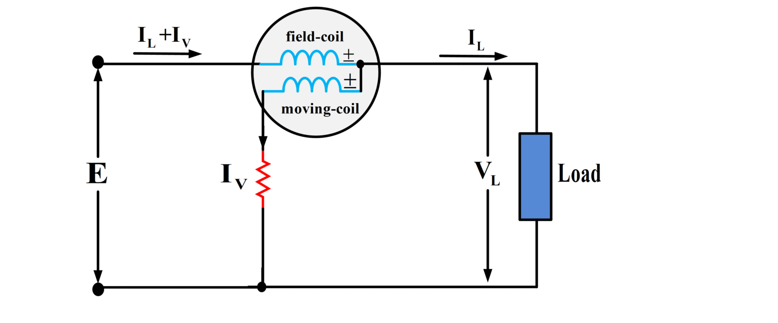
Consider the arrangement shown in figure 1(b). The moving coil of the instrument has a series resistor and is connected in parallel with the load. Consequently, current Iv through the moving coil is directly proportional to the load voltage. The field coils are connected in series with the load, so the current flowing through them is (IV+IL), as shown. If IV<<IL, IV can be neglected and the field coil current assumed to be approximately equal to IL. Because the meter deflection is proportional to the field coil current and to the moving-coil current,
\[\begin{align} & \text{defection }\alpha \text{ }{{\text{V}}_{\text{L}}}\text{ x }{{\text{I}}_{\text{L}}} \\ & \text{defection }\alpha \text{ P} \\\end{align}\]
Or
The scale of the instrument can be calibrated to indicate watts, and thus it becomes a dynamometer wattmeter. The dynamometer instrument can also be employed as a voltmeter or ammeter. For use as a voltmeter, the field coils are connected in series with the moving coil and a multiplier resistor. For ammeter applications, the field coils are connected in parallel with the moving coil, and in parallel with a shunt, as required.
Fig. 1(b): Dynamometer Wattmeter
Because fairly large currents are required to set up the necessary field flux, the dynamometer instrument is not as sensitive as a PMMC instrument. Consequently, its major application is as a wattmeter. One advantage that the dynamometer has over a PMMC instrument is that it can be used for both direct and alternating current/voltage measurements.
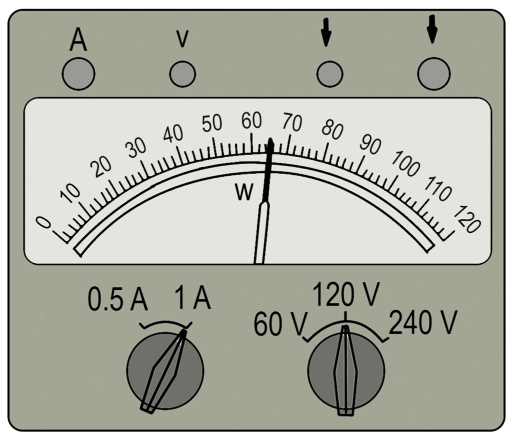
The scale of the wattmeter illustrated in Figure 2 is read directly only when the range switches are set to 1 A and 120 V. When set to 0.5 A and 60 V, FSD represents: (0 5 A X 60 V): 30 W.
Fig.2: Wattmeter Scale
It is important to avoid excessive current flow in the voltage and current coils of a wattmeter. When set to the 60 V range, the applied voltage should not exceed 60 V even when the pointer indication is less than full scale.


