At the present time, we are seeing a growing number of small energy suppliers using a variety of renewable energy sources to produce electricity.
Electricity from Wind Power
Wind power systems convert the kinetic energy in wind into electric energy. Wind turbines are installed in locations with strong, sustained winds. Figure 1 shows a wind turbine used to generate electricity. Its operation can be summarized as follows:
- The energy in the wind turns two or three propeller like blades around a rotor.
- The rotor is connected to the main shaft, which spins a generator to create electricity.
- Wind turbines are typically mounted on a tower at an elevation high above grade away from ground obstructions where wind currents are strong and consistent.
- To extract as much energy from the wind as possible, the wind turbine blades are huge—up to 330 feet tip to tip.
- Wind sensors enable the turbine’s computer to control the movement of the rotor and to produce optimum power in all wind conditions.
- Wind turbines are usually grouped together in what are called wind farms.
- The electrical power from the generator is typical 5-Hz, AC power with 50-volt output for large wind turbines. A transformer may be required to increase or decrease the voltage so it is compatible with the end use, distribution, or transmission voltage, depending on the type of interconnection.
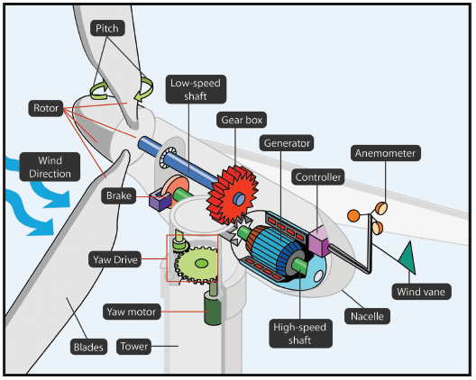
Figure 1 Wind turbine used to generate electricity.
Electricity from Solar Energy
Solar energy is energy harnessed from the sun. Solar electric or photovoltaic (PV) technology converts sunlight directly into electricity. Figure 2 illustrates a grid-tied solar system. Its operation can be summarized as follows:
- Grid-tied solar electric systems generate electricity for your home or business and route the excess power into the electric utility grid for compensation from the utility company.
- Photovoltaic (PV) panels gather solar energy in the form of sunlight and convert it into direct current (DC) electricity.
- The more sunlight the panels receive, the more electricity they produce.
- The inverter performs the conversion of the variable DC output of the PV panel into a clean sinusoidal 5-Hz AC current that is then applied directly to the commercial electric grid network.
- Net metering means the utility company charges you the difference between what you consume from the grid and the electricity you generate.
- Current from solar panels reverses the direction of the electric meter during the day as it flows back into the electric grid.
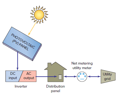
Figure 2 Grid-tied solar system.
Fuel Cell
A fuel cell is an electrochemical cell that converts chemical energy from a fuel such as hydrogen and an oxidant (air or oxygen) into electricity. In principle, a fuel cell operates much like a battery.
Unlike a battery however, a fuel cell does not run down or require recharging. It will produce electricity as long as fuel and an oxidizer are supplied. The block diagram of a hydrogen-oxygen fuel cell is shown in Figure 3 and operates as follows:
- The fuel cell device uses hydrogen fuel and oxygen to create electricity.
- The hydrogen can come from a variety of sources (hydrogen, natural gas, methanol, and gasoline).
- The cell contains an anode electrode, a cathode electrode and an ion-conducting material called an electrolyte.
- Hydrogen passes over one electrode and oxygen over the other, generating electricity, water, and heat.
- Fuel cells are classified by their electrolyte material.
- Hydrogen-oxygen fuel cells can be used to power vehicles as illustrated in Figure 4. These vehicles only emit water, instead of air pollutants, while they are operating.
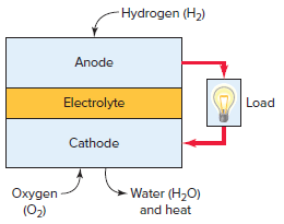
Figure 3 Hydrogen-oxygen fuel cell.
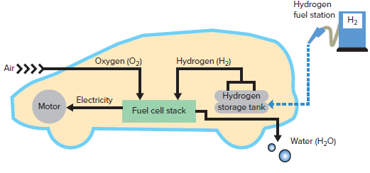
Figure 4 Fuel cell vehicle.
Cogeneration Power Systems
Cogeneration is the simultaneous production of heat (usually in the form of hot water and/or steam) and electric power, utilizing one primary fuel.
Facilities with cogeneration systems use them to produce their own electricity and use the unused excess (waste) heat for process steam, hot water heating, space heating, and other thermal needs.
Figure 5 illustrates a typical cogeneration system consisting of an engine or combustion turbine driving an electric generator. The operation of the system can be summarized as follows:
- The cogeneration process of converting fuel into electricity produces considerable amounts of heat.
- The heat recovery unit captures and makes use of the waste heat from the engine and exhaust gases by creating steam and/or hot water. This heat is then routed to the facility’s heat distribution system.
- The electricity created is tied into the main switch gear and operates in parallel with the local utility, reducing the facility’s electrical load on the local grid.
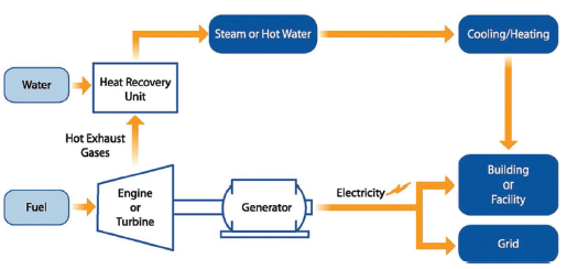
Figure 5 Typical cogeneration system.
Emergency Power Supply Systems
When power in an electrical system is disrupted for an extended period, life-threatening conditions may occur. Continuous lighting and power are essential in places of public assembly, theaters, hotels, sports arenas, health care facilities, and the like.
Engine-driven alternators are commonly used to provide emergency power in the event of a power failure. Figure 6 shows a residential standby generator unit that allows ongoing operation of essential loads during a utility outage. Such units include a small engine and generator mounted together and called a generator set.
Natural gas or liquid propane gas is a commonly used fuel source available for powering the engine. Normally the generator set is mounted on a cement pad, preferably near the fuel source.
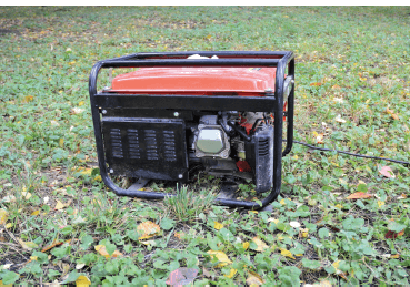
Figure 6 Residential standby generator.
Residential generator installations must be coordinated with the local electric utility, including obtaining any necessary approvals and taking all safety precautions to prevent feedbacks onto the utility system.
A common approach in the design of a standby system is to divide the dwelling’s circuits into essential and nonessential loads, as illustrated in Figure 7. The essential loads design approach requires a smaller generator with a lower-power rating. The operation of the system can be summarized as follows:
- Essential circuits have their own separate panel board.
- Nonessential circuits are supplied from the service panel board. This service panel board sub feeds the smaller essential loads panel through a transfer switch.
- If a utility power outage occurs, the transfer switch (either manual or automatic) changes from utility power to generator power.
- The nonessential loads in the service equipment are shed, and the generator supplies electricity only to the essential loads.
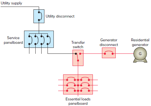
Figure 7 Essential loads standby generator design.
Even a brief power outage can result in loss of unsaved data on a personal computer (PC) that was running. An uninterruptable power supply (UPS) is designed to supply electricity to a load for a certain period of time during a utility failure.
UPS systems are normally designed to provide operating time during an interruption from 5 to 20 minutes. There are several basic methodologies used by manufacturers in the design of UPS systems.
Figure 8 shows the block diagram of an offline UPS system, the most commonly used type for small applications such as running a single desktop computer or workstation. The operation of the system can be summarized as follows:
- In normal operation, the main AC power input is supplied directly to the load.
- Should a voltage drop occur, the UPS then switches on instantaneously by means of a static switch to a battery-powered inverter, providing backup power to the load.
- The rectifier/charge regulator converts mains supply AC to DC, keeping the battery charged to full capacity. The charge regulator protects the battery bank from overcharge and prevents excessive discharge.
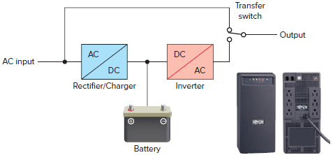
Figure 8 Typical offline UPS system.
Review Questions
- Explain how electricity is generated by a wind turbine.
- Explain how a grid-tied solar system works.
- List three types of fuels that can be used to create electricity from fuel cells.
- What are the two functions of a cogeneration system?
- How is electricity generated in a residential standby generator unit?
- Explain the essential loads approach to the design of an emergency power supply system.
- What is the main application for an uninterruptable power supply?
Answers
- Wind power systems convert the kinetic energy in wind into electric energy by turning blades connected to a generator.
- A grid-tied solar electric system generates DC power from the sun. The DC power is converted to AC and connected to the home electric distribution panel. The building’s electric meter measures the net power consumed by the building.
- Hydrogen, natural gas, methanol, or gasoline
- Produce heat and electricity.
- A small engine, fueled by natural gas or liquid propane gas, is connected to a generator to produce emergency power.
- The essential loads design approach requires a smaller generator with a lower-power rating by only supplying power to the essential circuits during a power outage.
- The main application of a UPS is to power small applications such as running a single desktop computer or workstation during a power outage.
