The article explains two-wire and three-wire motor control circuit, detailing their configurations and operations. It covers basic control systems, including manual and automatic controls, as well as the start/stop functionality and multiple start/stop stations for controlling motors remotely.
Basic control circuits are a combination of electrical logic formations of wires. These combinations are designed to enable a machine to complete specific tasks. Some of the most complex circuits in industry stem from some of the most basic control circuits electricians must learn and be able to sketch and wire at a moment’s notice.
The basic control circuits include two wire, three wire controls, manual /automatic, sequential control, stop/start, forward reverse, and jogging circuits.
Two-Wire Control
Two-wire control, as seen in configuration 1, consists of a control device containing one set of contacts used to facilitate the on an off operation of a pilot device.
Two wire controls are generally designed to carry small amounts of current. This type of control system cannot sufficiently handle large amounts of current nor control loads that require more than one set of contacts that is required for single phase 240V 208 V or 480/277 circuit.
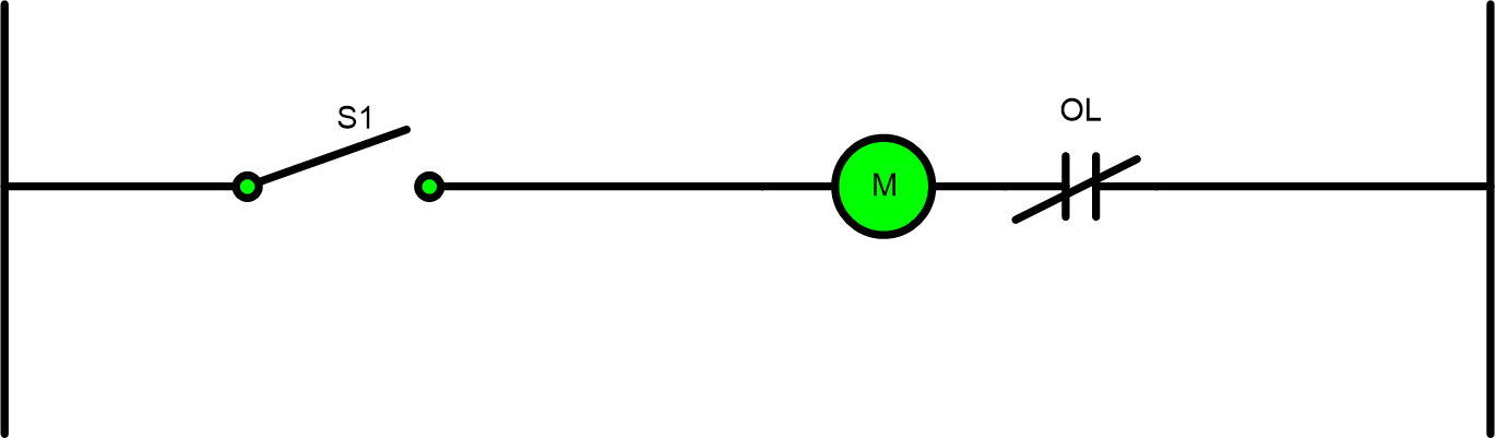
Two wire controls can be connected not only to turn on lights but they may be connected to control motors.
Configuration 1 illustrates a switch connected to a motor starter coil which turns on a motor or resistive load not shown in control diagrams. When the switch is closed voltage is transmitted to the relay type device energizing the solenoid of the motor pulling in the armature which results in the main contacts of the pilot device providing full line voltage to the load being controlled.
Just as a switch can be used in a two wire control system to manually control a load, a control device that is used to sense a change of pressure or physical location can be an automatic two wire control system.
In this system when the control device contact changes state due to an outside event without human intervention, this type of control circuit is called an automatic control circuit.
Automatic control systems are a load in a circuit that is activated by an event in a controlled environment without the need for human intervention. These systems are controlled by devices like a liquid level switch, pressure switch, float switch, flow switch, or any other device that census changes in a system automatically. Automatic control systems are at the heart of manufacturing. As the product is created there are a plethora of control devices that feed back into the control system to provide precision of movement and timing.
Manual and Automatic Controls
Mostly referred to as hand-off- auto, a two wire control system is constructed to facilitate either the manual operation of a load by maintaining power to the coil through a toggle switch as seen in the diagram below, or automatically controlled by a control device similar to a liquid level switch.
When the toggle switch is not activated or on, the automatic control device like a float or limit switch is connected in parallel so that some type of event would cause a control device to cut the load on or off without the presence of a operator.
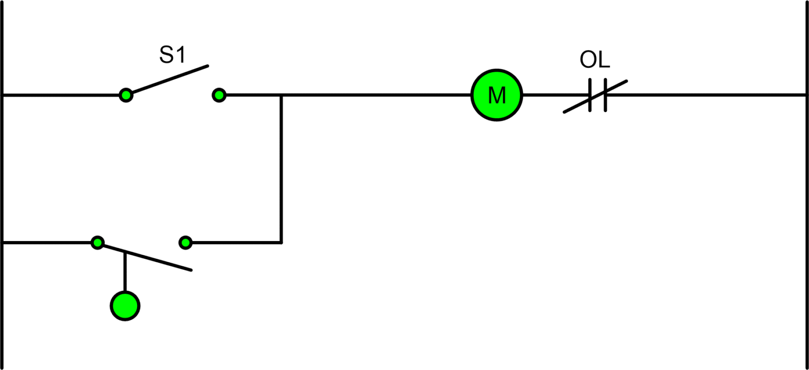
Configuration 2. Two wire Circuit
The two wire circuit in Configuration 2 operates as follows:
- If the single pole switch is toggle closed, the motor starter will start and stay on for as long as the single pole switch is closed.
- If the single pole switch marked S1 is left open, then the liquid level switch in the circuit will now be the control device that turns the motor starter on or off.
- In this circuit, the load will always be on unless power is lost to the entire control circuit because either the single pole switch could be the activating factor or at any given moment the liquid level switch could energize the coil of the motor starter in the control circuit.
Three-Wire Control
The most basic three wire control circuit is the start/stop circuit. The basic operation of the stop/start circuit is to provide a means of remotely controlling a motor operated load from a panel that only contains the low voltage control circuitry.
A three wire control circuit uses momentary contact, start/stop stations, and a normally open seal in contact connected in parallel with the start button to maintain voltage to the coil.
The set up for the three wire sire control circuit is different from the two wire operation because there are less components needed to operate the load. The three wire device’s various parts may vary from one manufacturer’s switch to another, but the basic circuit remains the same.
Stop/Start Control Circuit Operation
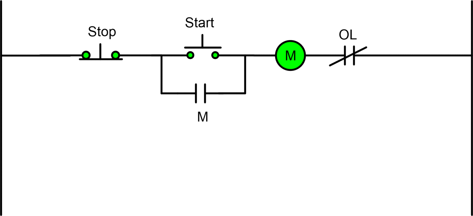
Configuration 3. Stop/Start Circuit
The Stop/Start circuit in Configuration 3 operates as follows:
- The start pushbutton is pressed sending power to the coil.
- Once the coil is energized the armature of the pilot device closes along with the memory/seal-in contact.
- The seal-in contact maintains power to the coil overriding the need for the start pushbutton to continue being pressed.
- The load connected to the motor starter (M) receives full voltage from the line and will continue running until the stop pushbutton is pressed or the motor should go into overload.
- Pressing the stop pushbutton breaks the control voltage through the memory/seal-in contact causing the coil to de-energized which open the line voltage to the loads turning it off.
Multiple Start/Stop Stations Controlling a Motor
Sometimes it is necessary to control a load from more than one location. The diagram below illustrates the control circuit needed to accomplish the operation.
First, the stop pushbuttons are connected in series to form a NOR logic. Next, the start pushbuttons are connected in parallel to form an OR logic circuit. This control circuit is a variation of the three wire control circuit.
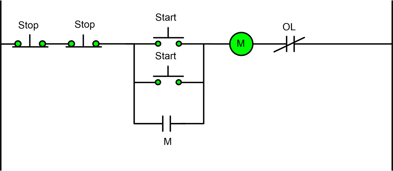
Configuration 4. Multiple Stop/Start Circuit
This Multiple Stop/Start circuit in Configuration 4 operates as follows:
- Either start pushbuttons can be pressed to energize the coil.
- The energizing of the coil causes the armature of the motor starter to close and along with it the seal-in contact that servers to maintain power to the coil overriding the need for the start pushbuttons to be pressed.
- Full line voltage is sent to the load connected to the motor starter.
- The motor starter will continue to run until either of the start pushbuttons is pressed or an overload should occur.
- Once the stop pushbuttons are pressed power to the memory/seal-in contact is lost causing the armature of the coil to open the main contacts.
Two Wire & Three Wire Motor Control Circuit Key Takeaways
In conclusion, two-wire and three-wire motor control circuit are essential for various industrial applications due to their simplicity and efficiency in controlling machinery and motor-operated loads. These control systems, whether manual or automatic, allow for remote management, precise timing, and automation, making them integral in manufacturing processes, improving operational safety, and reducing human intervention in critical tasks.