This guide covers Unijunction Transistor (UJT) Operation, Characteristics Curve, and Applications along with circuit diagrams.
A unijunction transistor (UJT) is a three-electrode device that contains one PN junction consisting of a bar of N-type material with a region of P-type material doped within the N-type material. See Figure 1.
The N-type material functions as the base and has two leads, base 1 (B1) and base 2 (B2). The lead extending from the P-type material is the emitter (E).

Figure 1. A unijunction transistor (UJT) consists of a bar of N-type material with a region of P-type material doped within the N-type material.
In the schematic symbol for a UJT, an arrowhead represents the emitter (E). Although the leads are usually not labeled, they can be easily identified because the arrowhead always points to B1. The case of a UJT may include a tab to identify the leads. See Figure 2.

Figure 2. In the schematic symbol for a UJT, an arrowhead represents the emitter (E) and always points to base 1 (B1).
A UJT is used primarily as a triggering device because it generates a pulse used to fire SCRs and triacs.
Outputs from photocells, thermistors, and other transducers can be used to trigger UJTs, which in turn fire SCRs and triacs. UJTs are also used in oscillators, timers, and voltage-current sensing applications.
Unijunction Transistor (UJT) Characteristic Curve
In normal operation, B1 is negative and a positive voltage is applied to B2. The internal resistance between B1 and B2 is divided at E, with approximately 60% of the resistance between E and B1. The remaining 40% of the resistance is between E and B2. The net result is an internal voltage split. This split provides a positive voltage at the N-type material of the emitter junction, creating a reverse-biased emitter junction.
As long as the emitter voltage remains less than the internal voltage, the emitter junction will remain reverse biased, even at a very high voltage. However, if the emitter voltage rises above this internal value, a dramatic change will take place.
When the emitter voltage is greater than the internal value, the junction becomes forward biased. Also, the resistance between E and B1 drops rapidly to a very low value.
A UJT characteristic curve shows the dramatic change in voltage due to this change in resistance. See Figure 3.
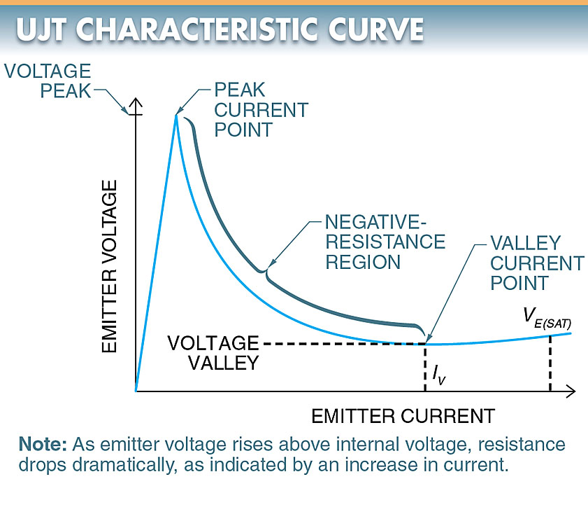
Figure 3. A UJT characteristic curve shows the dramatic change in voltage due to a rapid change in resistance. The negative-resistance region is ideal for triggering.
Unijunction Transistor (UJT) Operation
As long as the E-B1 junction is reverse biased and no current flows into the emitter, the current flow in the N-type material should be minimal. This is due to the small amount of doping that creates a high resistance.
When the E-B1 junction is forward biased, the junction turns on, causing carriers to be injected into the base region. These carriers create an excess of holes. Their presence in the N-type material increases conductivity, which lowers the resistance of the region.
Once started, current flows easily between B1 and E. Therefore, the conductivity of this region is controlled by the flow of emitter current.
Triggering Circuits
A UJT is typically used as a triggering circuit for a triac or similar device.
When switch S1 is closed, the voltage- divider action of the UJT produces a voltage between B1 and the N-type material of the emitter junction.
At this same instant, the emitter voltage is zero since it is tied to capacitor C1. The emitter junction at that point is reverse biased and no current flows through the junction.
As capacitor C1 begins to charge through resistor R1, the voltage across capacitor C1 should begin to increase.
For an emitter to be forward biased, it must be more positive than the base (+0.6 V for silicon or +0.2 V for germanium).
Assuming a silicon crystal is used in the UJT, the junction becomes forward biased when the control voltage reaches 0.6 V beyond the junction voltage.
With the junction forward biased, the internal resistance of the E-B1 region drops dramatically. This causes capacitor C1 to discharge its energy through base load resistor R3. See Figure 4.
Once the capacitor has discharged enough to reduce the forward bias on the junction, the resistance of the junction returns to normal.
The cycle of capacitor charging and discharging then repeats.
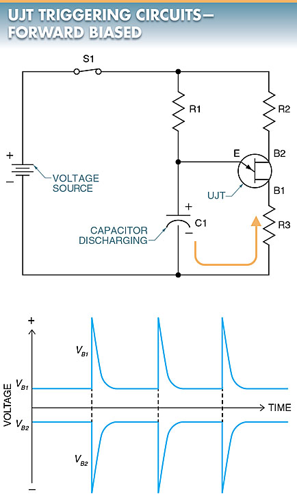
Figure 4. With the emitter junction forward biased, the internal resistance of the E-B1 region drops dramatically and causes capacitor C1 to discharge its energy through base load resistor R3.
Each time the emitter becomes forward biased, the total resistance between B1 and B2 drops, permitting an increase in current through the UJT. As a result, a positive pulse (VB1) appears at B1 and a negative pulse (VB2) appears at B2 at the time the capacitor discharges.
Note: The repetition rate, or frequency, of the discharge voltage, is determined by the values of resistor R3 and capacitor C1. Increasing either one makes the device run more slowly. The pulses that appear across bases B1 and B2 are very useful in triggering SCRs and triacs.
Unijunction Transistor (UJT) Applications
The UJT is used in switching and timing applications. A UJT often reduces the number of components needed to perform a given function.
The number of components is often less than half of what is required when using bipolar transistors.
Emergency Flashers
A UJT can serve as a triggering circuit for an emergency flasher. As a triggering circuit, UJT Q1 provides base bias to drive transistors Q2 and Q3 through resistors R2 and R3. Transistors Q2 and Q3 are used to light an incandescent lamp load. See Figure 5.
The circuit repetition rate (frequency) is determined by the characteristics of the UJT, supply voltage, and emitter RC time constant of Q1.
To change the flashing rate, the value of capacitor C1 must be changed. As capacitor C1 increases in value, the flashing rate decreases. As capacitor C1 decreases in value, the flashing rate increases.
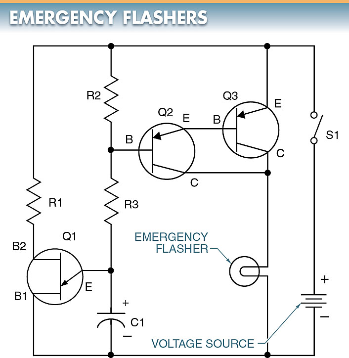
Figure 5. A UJT can serve as a triggering circuit for an emergency flasher.
Tech Fact
A UJT can be considered as a diode connected to a voltage divider network. UJTs have the ability to be used as relaxation oscillators.
An oscillator is a circuit that produces a repetitive electronic signal, such as a sine wave, without AC input signals.
Relaxation oscillators are characterized internally by short, sharp pulses of waveforms that can potentially trigger gates.
Unijunction Transistor (UJT) Key Takeaways
Understanding the operation, characteristic curve, and applications of the Unijunction Transistor (UJT) is essential due to its versatility and efficiency in electronic circuit design. Its unique negative-resistance property allows it to function as a reliable triggering device in oscillators, timers, and switching circuits, reducing component count and complexity. UJTs are especially valuable in applications such as SCR/triac firing, emergency flashers, and voltage/current sensing circuits where precise control of timing and pulses is crucial.