The article discusses the use of transistor as electronic switches and compares them with mechanical switches, highlighting the advantages of solid-state switching devices. It also explains how to test a transistor using a digital multimeter by checking its junctions for shorts or opens.
Mechanical switches have the advantages of being able to switch either AC or DC, having only two operating conditions (open or closed), and being easy to understand and troubleshoot.
Mechanical switches have the disadvantages of having a much shorter operating life than solid-state switches and producing arcing at the contacts, which can be dangerous in some applications.
Solid-state switches such as silicon-controlled rectifiers (SCRs) and triacs can replace mechanical switches. Solid-state switches have a much longer operating life, can control the amount of voltage/current between being totally open or closed, and do not produce arcing since there are no contacts.
Solid-state switches have the disadvantages of being able to switch only AC or DC, being harder to understand, and requiring more knowledge of the circuit and components when a technician troubleshoots them.
It is important to understand solid-state switches since they are being used more often to replace mechanical switches in circuits and switching applications.
Solid-State Switches
Solid-state switches are electronic devices that have no moving parts (contacts). Solid-state switches can be used in most motor control applications.
The advantages of solid-state switches include fast switching, no moving parts, long life, and the ability to be interfaced with electronic circuits (PLCs and PCs). However, solid-state switches must be properly selected and applied to prevent potential problems.
Solid-state switches include transistors, silicon-controlled rectifiers (SCRs), triacs, diacs, and unijunction transistors (UJTs). See Figure 1.
Triacs, diacs, and unijunction transistors (UJTs), along with SCRs, are often found in the same circuitry. Triacs and SCRs are control devices.
Diacs and UJTs form the triggering circuits for triacs and SCRs. Triacs, diacs, UJTs, and SCRs operate only as switches and may be used in a variety of switching applications.
Tech Fact
Solid-state switches have a switch life in the billions of cycles while mechanical switches have a switch life of about 200,000 cycles, making solid-state switches the standard for most high-volume switching applications.
Transistors as a Switch
A transistor is a three-terminal device that controls current through the device depending on the amount of voltage applied to the base. Transistors may be NPN or PNP transistors. Transistors can be switched on and off quickly.
Transistors have a very high resistance when open and very low resistance when closed. Transistors are used to switch low-level DC only. When transistors are used as switches, a diode can be mounted across the transistor to prevent damage from high-voltage spikes (transients).
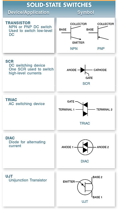
Figure 1. Solid-state switches include transistors, silicon- controlled rectifiers (SCRs), triacs, diacs, and unijunction transistors (UJTs).
Transistors as DC Switches
Transistors were mainly developed to replace mechanical switches. Transistors have no moving parts and can switch on and off quickly.
Mechanical switches have two conditions: open and closed or ON and OFF. Mechanical switches have a very high resistance when open and very low resistance when closed.
A transistor can be made to operate like a switch. For example, a transistor can be used to turn on or off a pilot light. See Figure 2.

Figure 2. A transistor can be made to operate like a switch.
In this circuit, the resistance between the collector (C) and the emitter (E) is determined by the current flow between the base (B) and emitter (E). When no current flows between B and E, the collector-to-emitter resistance is high, like that of an open switch. The pilot light does not glow because there is no current flow.
If a small current flow between B and E, the collector-to-emitter resistance is reduced to a very low value, like that of a closed switch. The pilot light is switched on.
A transistor switched on is normally operating in the saturation region. The saturation region is the maximum current that can flow in a transistor circuit.
At saturation, the collector resistance is considered zero and the current is limited only by the resistance of the load.
When the circuit reaches saturation, the resistance of the pilot light is the only current-limiting device in the circuit.
When the transistor is switched off, it is operating in the cutoff region. The cutoff region is the point at which the transistor is turned off and no current flows.
At cutoff, all the voltage is across the open switch (transistor) and the collector-emitter voltage is equal to the supply voltage VCC.
Transistor Applications
Transistors are used for switching because of their reliability and speed. In certain situations, transistors are also integrated with other solid-state components to form more complex devices.
In each application, however, the fundamental operating principle of the transistor remains the same.
Seven-Segment Displays
By switching various combinations of transistors on or off, different numbers can be created on a seven-segment display. See Figure 3.
For example, if all transistors (A through G) are switched on, an “8” should appear on the display. If all transistors, except E and D, are switched on, a “9” should appear. There is typically circuitry in addition to the seven-segment transistor devices to help decode the proper signals for the display.
When all circuitry is present, it is called a seven-segment decoder/driver display or readout device.
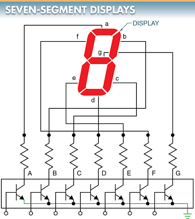
Figure 3. When various combinations of transistors are switched on and off, different numbers appear on a seven-segment display.
Testing Transistors Using a Digital Multimeter
A transistor becomes defective from excessive current or temperature. A transistor normally fails due to an open or shorted junction. The two junctions of a transistor may be tested with a digital multimeter (DMM) set to measure resistance. See Figure 4.
To test an NPN transistor for an open or shorted junction, the following procedure is applied:
- Connect a DMM to the emitter and base of the transistor. Measure the resistance.
- Reverse the DMM leads and measure the resistance. The emitter/base junction is good when the resistance is high in one direction and low in the opposite direction.
Note: The ratio of high to low resistance should be greater than 100:1. Typical resistance values are 1 kΩ with the positive lead of the DMM on the base and 100 kΩ with the positive lead of the DMM on the emitter. The junction is shorted when both readings are low. The junction is open when both readings are high.
- Connect the DMM to the collector and base of the transistor. Measure the resistance.
- Reverse the DMM leads and measure the resistance. The collector/base junction is good when the resistance is high in one direction and low in the opposite direction.
Note: The ratio of high to low resistance should be greater than 100:1. Typical resistance values are 1 kΩ with the positive lead of the DMM on the base and 100 kΩ with the positive lead of the DMM on the collector.
- Connect the DMM to the collector and emitter of the transistor. Measure the resistance.
- Reverse the DMM leads and measure the resistance. The collector/emitter junction is good when the resistance reading is high in both directions.
The same test used for an NPN transistor can be used for testing a PNP transistor. The difference is that the DMM test leads must be reversed to obtain the same results.
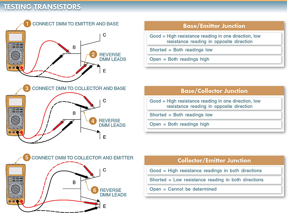
Figure 4. A transistor normally fails due to an open or shorted junction.
Transistor as a Switch Key Takeaways
Understanding the operation and advantages of solid-state switches, particularly transistors, is essential in modern electronics due to their vast range of practical applications. Unlike mechanical switches, solid-state devices offer faster switching speeds, longer life spans, and improved reliability, making them ideal for integration in electronic systems such as motor controls, digital displays, and computing devices. Their use in precision control, low-power switching, and high-frequency circuits underscores their importance in industries ranging from automation to consumer electronics. As technology continues to advance, the role of transistors and other solid-state switches will only grow, making their knowledge and correct application critical for technicians and engineers alike.