The article provides an overview of half-wave and full-wave rectifier, explaining how diodes are used to convert alternating current (AC) into pulsating direct current (DC). It also discusses the bridge rectifier, a type of full-wave rectifier that uses four diodes to improve efficiency without requiring a center-tapped transformer.
A diode is a very useful component when it is necessary to convert an alternating current into a pulsating direct current.
Half-Wave Rectifier
The simple half-wave rectifier circuit diagram is shown in Figure 1.
When the input voltage is on its positive half cycle, the diode conducts (the diode is placed in forward bias), current flows, and a voltage appears across the load resistor.
During the negative half cycle, the diode is reverse biased and does not conduct. There is no current in the circuit and no voltage drop across the resistor. The pulsating voltage across the load R is illustrated in Figure 1.
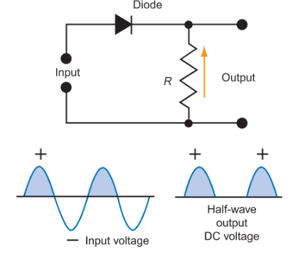
Figure 1. A diode converts an ac voltage to a pulsating dc voltage. The diode conducts only during the positive cycle of the ac input wave. The output waveform represents a half-wave, pulsating direct current.
Full-Wave Rectifier
Since only half of the wave is used in a half-wave rectifier circuit, more efficient power supplies have been developed to use both halves of the sine wave. These circuits are called full-wave rectifiers. In Figure 2, a circuit diagram of full-wave rectifier power supply shows the path of current in the secondary of the transformer from A to B.
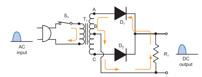
Figure 2. Full-wave rectifier current for the positive alternation of the sine wave.
Note that diode D1 in Figure 2 is forward biased (conducting) during the positive alternation of the sine wave. Diode D2 is in reverse bias (non-conducting), and acts as an open circuit. Current is generated in the top half of the secondary coil of T1 (points A and B) and flows to the load resistor R1 and back toward D1. The resistor R1 sees the current flow and a voltage drop is generated across it.
During the next half cycle, the current reverses direction in the primary and secondary of T1. See Figure 3. Now the current flows from C to B in the secondary. At this time, diode D1 is in reverse bias (open circuit) and diode D2 is conducting (closed circuit). Current flows from point C to point B, through the load resistor, R1, and back to diode D2. Note, however, that the current still flows in the same upward direction through resistor R1. Again, as current flows within resistor R1, a voltage drop is generated across it.
The applied ac sine waveform sent to the rectifier from the secondary of the transformer has been changed into full-wave pulsating direct current.
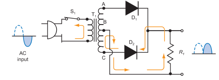
Figure 3. Full-wave rectifier current for the negative alternation of the sine wave.
Bridge Rectifier
The bridge rectifier circuit is another type of full-wave rectifier circuit that uses four diodes. The primary difference of this circuit and the last is the transformer. The two-diode full-wave rectifier uses a center- tapped transformer for the secondary winding.
The bridge rectifier transformer does not need the center tap. It instead uses two more diodes. Oftentimes, these four diodes are packaged within a single case for ease of application.
In the bridge rectifier circuit, two diodes are forward biased at any given time. Likewise, the other two diodes are in reverse bias.
Figure 4 depicts a bridge rectifier circuit diagram. Depending upon the polarity of the current flow from the secondary of the transformer, two diodes are conducting, while two diodes are non-conducting.
If the polarity at point A is positive, and point B is negative, diodes D2 and D4 are conducting. Current is flowing in an upward direction in the load resistor, R1. Diodes D1 and D3 are reverse biased and acting as an open switch. When the polarities change, making point A negative and point B positive, the diodes that conduct and do not conduct switch. In this case, diodes D1 and D3 conduct, while diodes D2 and D4 are not conducting. Again, the current flows upward through the load resistor, and full-wave pulsating direct current is found at the output.
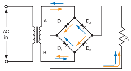
Figure 4. A bridge rectifier circuit with a pulsating dc output.
Half and Full Wave Rectifier Key Takeaways
Half-wave, full-wave, and bridge rectifiers play a crucial role in converting alternating current into a usable form of direct current, which is essential for powering a wide range of electronic devices. Their ability to provide a stable DC output makes them vital components in applications such as power supplies, battery chargers, and various electronic circuits, ensuring the reliable and efficient operation of modern technology.