The article provides an overview of solid-state motor starters, explaining their components, wiring, overload protection, and starting modes. It also outlines how these starters use electronic controls to manage motor performance, improve efficiency, and reduce mechanical stress during motor operation.
A solid-state motor starter is an electronically operated switch (contactor) that uses solid-state components to eliminate mechanical contacts and includes motor overload protection. Solid-state motor starters are connected into a circuit after the disconnect/overcurrent protection device and before the motor.
Solid-state motor starters include motor overload protection and are controlled by the same switches (pushbuttons, pressure switches, etc.) as electromechanical starters. See Figure 1.
Solid-state motor starters consist of solid-state components such as SCRs or triacs that allow current flow when they are conducting and stop current flow when they are not conducting.
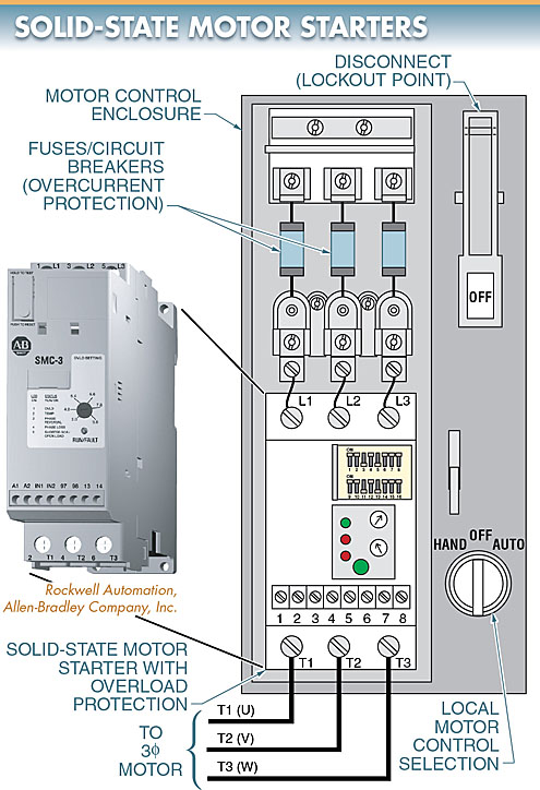
Figure 1. Solid-state motor starters eliminate electromechanical components by using solid-state components to turn a motor on and off.
Solid-State Motor Starter Components
Solid-state motor starters have terminals for connecting the incoming supply power (L1/R, L2/S, L3/T) and terminals for connecting a motor (T1/U, T2/V, T3/W). Solid-state motor starters also include a terminal strip for connecting external inputs (pushbuttons, proximity switches, etc.).
Solid-state motor starters also include a dual inline package (DIP) switchboard for programming starter functions (starting mode/time, stopping mode, etc.), and potentiometers for adjusting motor full-load current (in amps) and trip class. Solid-state motor starters may also include LEDs to provide a visual indication of circuit conditions. See Figure 2.
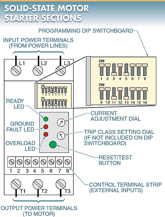
Figure 2. Solid-state motor starters have a control terminal strip, input and output power terminals, dials for current and trip class adjustment, and programming DIP switches.
Wiring Power and Control Circuits
The power circuit of a solid-state motor starter is wired by bringing power from the fuses/circuit breaker into the starter. The incoming power must be at the same voltage level for which the motor is rated or wired. See Figure 3.
The control circuit is wired to the control terminal strip located on the starter. The control circuit voltage is less than the power circuit voltage (typically 12 VDC, 12 VAC, 24 VDC, or 24 VAC).
The control terminal strip includes a connection for external control voltage (when required), connections for external control switches (pushbuttons, temperature switches, etc.), and connections for output contacts (alarms, indicating lamps, etc.) that can be used for controlling external loads.
Setting Overload Protection
Motors must be protected from overcurrents and overloads. Fuses and circuit breakers (normally located in the motor disconnect) are used to protect a motor from overcurrents (short circuits and high operating currents).
Overloads located in the motor starter protect the motor from overload current caused when the load on the motor is greater than the design torque rating of the motor. Overloads can be thermal overloads (heaters) or solid-state overloads.
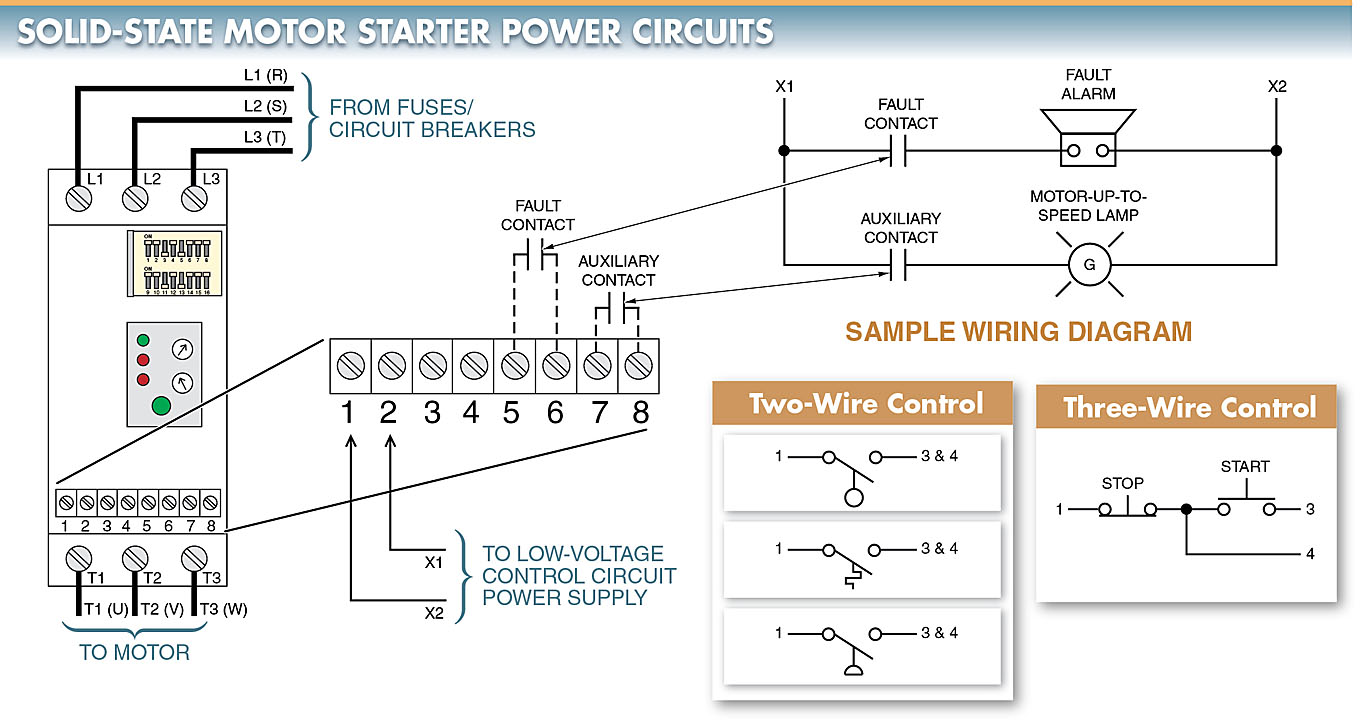
Figure 3. The power circuit of a solid-state motor starter is wired by bringing power from the fuses/circuit breaker into the starter. The control circuit is wired to the control terminal strip located on the starter.
Solid-state overloads use a current transformer (CT) to monitor each power line. Solid-state overloads are set by selecting a current limit based on full-load current ratings listed on the motor nameplate and the trip class setting (class 10, 15, 20, or 30). The current limit is set by adjusting the current adjustment dial located on the starter.
The trip class setting is the length of time it takes for an overload relay to trip and remove power from the motor.
The lower the trip class setting, the faster the trip time of the solid-state overload. The higher the trip class setting, the slower the trip time of the solid-state overload. The trip class setting is based on the motor application (a type of load placed on the motor). The trip class setting may be adjusted using a trip class setting dial located near the current adjustment dial or by using DIP switches. See Figure 4.
Cold trip is the trip point from the time the motor starts until the first time the overloads trip (motor operating below nameplate rated current). Hot trip is the trip point after the overloads have tripped and have been reset (motor operating near or over nameplate rated current).
Tech Fact
Magnetic motor starter overloads usually have a class 20 trip rating. Solid-state starters or drives have a class 10 trip rating. A slower trip time is usually programmed by selecting a class number or, if a number is unavailable, a “fast/minimum” or “slow/ maximum” rating.
Solid-State Starting
A solid-state reduced-voltage starter ramps up the motor voltage as the motor accelerates, instead of applying full voltage instantaneously like across-the-line starters do. Solid-state starters reduce inrush current compared to the high inrush current across-the-line starters produce.
Solid-state starters also minimize starting torque, which can damage some loads connected to the motor and smooth motor acceleration. See Figure 5.
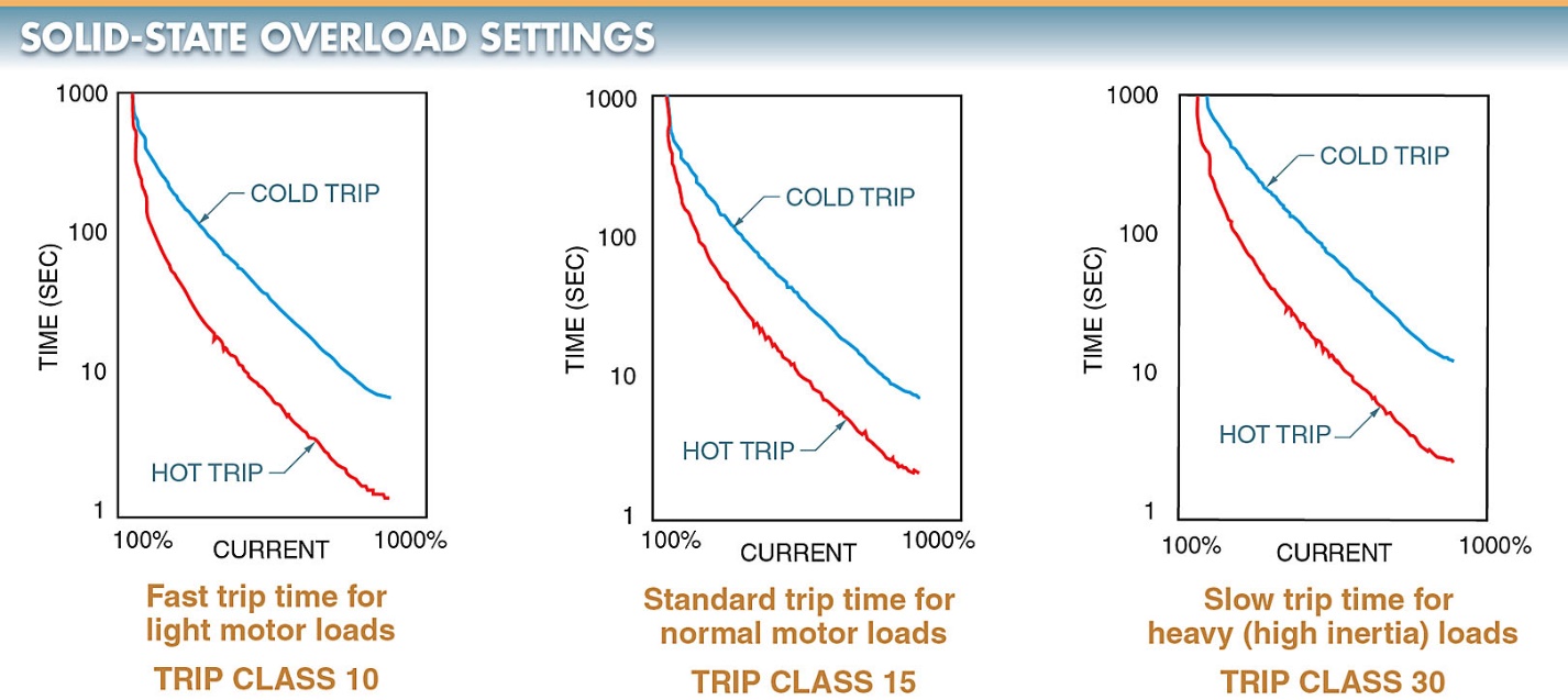
Figure 4. The trip class setting of solid-state overloads is based on the motor application (a type of load placed on the motor.
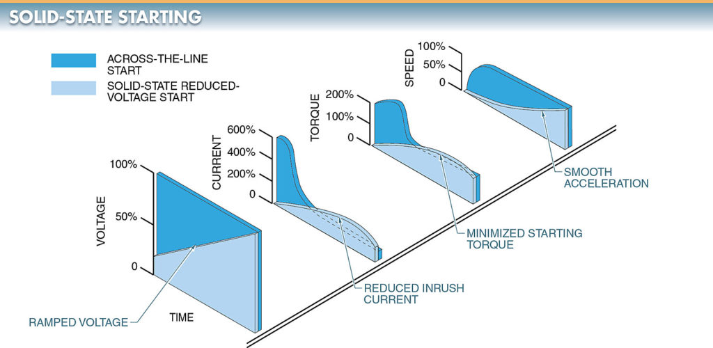
Figure 5. A solid-state starter ramps up the voltage reduces inrush current, minimizes starting torque, and smooths acceleration.
Solid-state starting provides a smooth, stepless acceleration in applications that require it, such as starting conveyors, compressors, pumps, and a wide range of other industrial applications because of its unique switching capability.
Electronic Control Circuitry
A solid-state controller determines to what degree the SCRs should be triggered on to control the voltage, current, and torque applied to a motor.
A solid-state controller also includes current-limiting fuses and current transformers for protection of the unit. The current-limiting fuses are used to protect the SCRs from excess current. The current transformers are used to feed information back to the controller. Heat sinks and thermostat switches are also used to protect the SCRs from high temperatures.
The controller also provides the sequential logic necessary for interfacing other control functions of the starter, such as line loss detection during acceleration. The controller is turned off if any voltage is lost or too low on any one line. This may happen if one line opens or a fuse blow.
Solid-State Starting Circuits
A typical solid-state starting circuit consists of both start and run contactors connected in the circuit. The start contactor contacts C1 are in series with the SCRs and the run contactor contacts C2 are in parallel with the SCRs. See Figure 6.
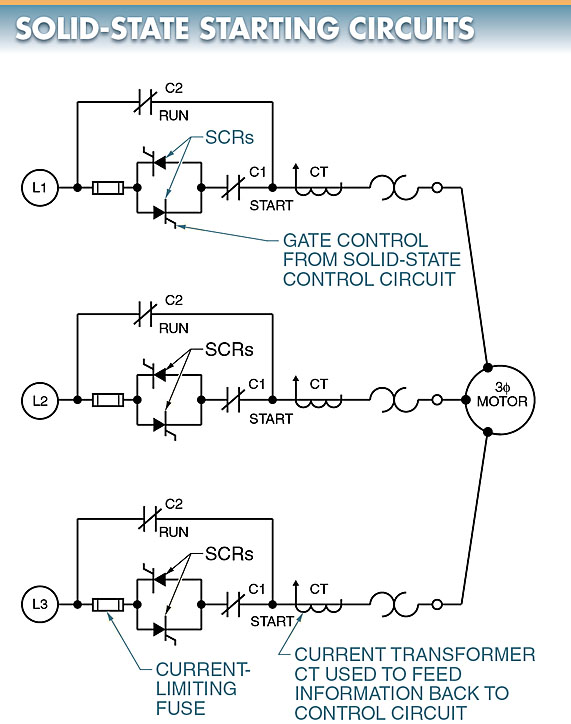
Figure 6. An SCR circuit with reverse-parallel wiring of SCRs provides maximum control of an AC load.
The start contacts C1 close and the acceleration of the motor is controlled by triggering on the SCRs when the starter is energized. The SCRs control the motor until it approaches full speed, at which time the run contacts C2 close, connecting the motor directly across the power line. At this point, the SCRs are turned off, and the motor runs with full power applied to the motor terminals.
Motor Starting Modes
Electromechanical and solid-state motor starters can be used to start a motor. When an electromechanical motor starter is used, the motor is connected to the full supply voltage.
When a motor is connected to full supply voltage, the motor has the highest possible current draw, the highest possible torque applied to the load, and the shortest acceleration time. This operating condition may be acceptable for some loads. However, many loads cannot be started with high starting torque because they control light loads (small parts, etc.) or delicate loads (paper rolls, etc.).
High starting current can also damage the power distribution system and trip breakers or blow fuses. Solid- state motor starters can be programmed for different starting modes to help reduce problems caused by full-voltage starting.
Motor starting modes include soft start, soft start with start boost, and current-limit start. See Figure 7.
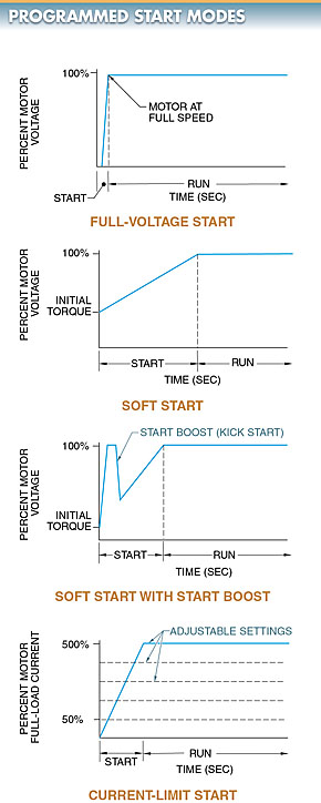
Figure 7. Solid-state motor starters can be programmed for different starting modes to help reduce problems caused by full-voltage starting.
Soft Start
Soft start is the most common solid-state starting method. When a starter is set for soft start, the motor is gradually accelerated over a programmable time period, normally 0 sec to 30 sec.
Common start time periods include 2 sec, 4 sec, 6 sec, 8 sec, or 16 sec. The starting torque is adjustable to a percent of the motor’s locked rotor torque. Common starting torque settings include 15%, 25%, 50%, or 60%. A soft start helps cushion the stress applied to loads connected to the motor.
Soft starting is achieved by increasing the motor voltage in accordance with the setting of the ramp-up control. A potentiometer is used to set the ramp-up time (normally 1 sec to 20 sec). Soft stopping is achieved by decreasing the motor voltage in accordance with the setting of the ramp-down control.
A second potentiometer is used to set the ramp-down time (normally 1 sec to 20 sec). A third potentiometer is used to adjust the starting level of motor voltage to a value at which the motor starts to rotate immediately when soft starting is applied. See Figure 8.
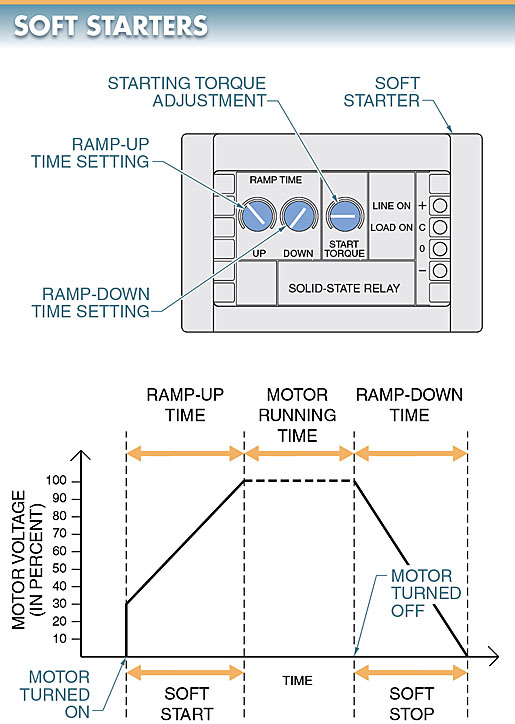
Figure 8. A soft starter is a device that provides a gradual voltage increase (ramp up) during motor starting and a gradual voltage decrease (ramp down) during motor stopping.
Like any solid-state switch, a soft starter produces heat that must be dissipated for proper operation. The heat dissipation requires large heat sinks when high-current loads (motors) are controlled. For this reason, a contractor is often added in parallel with a soft starter.
The soft starter is used to control the motor when the motor is starting or stopping. The contactor is used to short out the soft starter when the motor is running. This allows for soft starting and soft stopping without the need for large heat sinks during motor running. The soft starter includes an output signal that is used to control the time when the contactor is ON or OFF. See Figure 9.
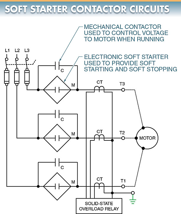
Figure 9. A contactor is used with a soft starter to control the voltage to the motor when the motor is running.
Soft Start with Start Boost
When a solid-state motor starter is set for soft start with start boost, the motor is given a current pulse during starting to provide additional starting torque for loads that are difficult to start.
The boost time is usually adjustable from 0 sec to 2 sec. The start boost is normally applied when there is a problem starting a motor using only a soft start.
Programming Solid-State Motor Starters
A solid-state motor starter must be programmed for proper operation before any power is applied to the starter. A solid-state motor starter is programmed by setting each DIP switch to a predetermined position based on motor and application requirements.
The number of DIP switch parameters can range from a few parameters (4 to 6) to numerous parameters. The higher the number of parameters that are available, the greater the number of applications for which the starter can be used. See Figure 10.
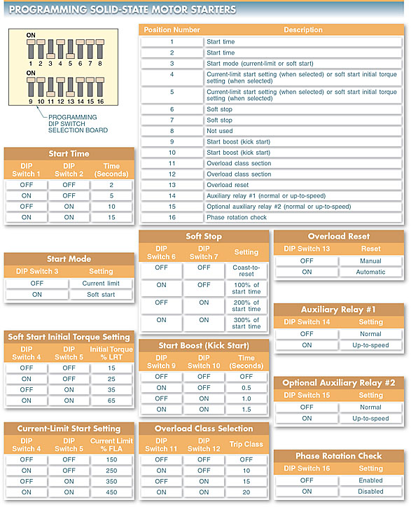
Figure 10. A solid-state motor starter is programmed by setting each DIP switch to a predetermined position based on motor and application requirements.
DIP switch parameters include motor starting mode (start time, soft start, start boost, etc.) and the operation of auxiliary contacts (when they are open or closed).
Each DIP switch setting must be understood and checked before any power is applied to the starter because some settings can be critical to protecting workers, the motor, and the system.
For example, the overload reset function can be placed in a manual or automatic mode. In the manual mode, the reset button on the starter must be pressed before the motor can be restarted manually (by external pushbuttons, etc.).
However, in the automatic reset mode, the starter automatically restarts the motor after a short time period if the external control switch (pressure switch, etc.) is still closed. This can cause a safety hazard if the person working on or around the system does not know the motor may automatically restart. For this reason, it is important to always refer to the manufacturer literature regarding the setting and meaning of each DIP switch position.
Motor Stopping Modes
Electromechanical and solid-state motor starters can be used to stop a motor when power is removed. When an electromechanical starter is used, the motor coasts to a stop at a rate determined by the load connected to the motor.
Solid-state motor starters can be programmed for different stopping modes. This allows greater application flexibility and protection of the motor/load. Motor stopping modes include a soft stop, pump control, and brake stop. See Figure 11.
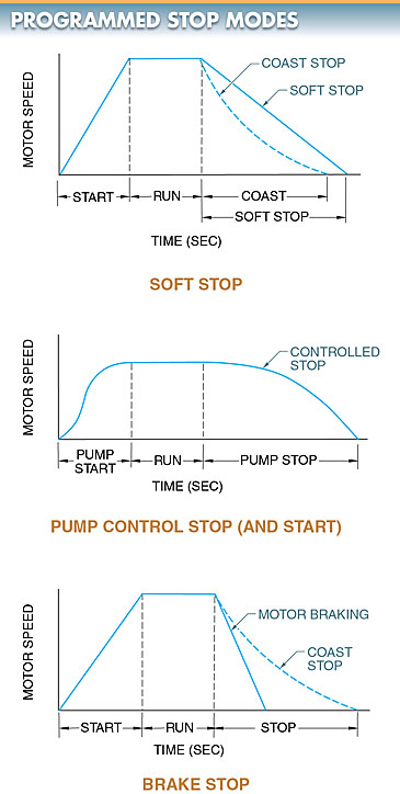
Figure 11 Solid-state motor starters can be programmed for different stopping modes to allow greater application flexibility and protection of the motor/load.
Soft Stop
The soft stop is the most common solid-state motor starter stopping method. Soft stops allow for an extended controlled stop. In a soft stop, the deceleration time is controlled by the starter, not the load. The soft stop mode is designed for friction loads that tend to stop suddenly when a voltage is removed from the motor.
Pump Control
The pump control mode is used to reduce surges that occur when centrifugal pumps are started and stopped. The pump control mode produces smooth acceleration and deceleration of motors and pumps.
Common motor and pump starting times range from a few seconds to 30 sec. Common motor and pump stopping times range from a few seconds to 120 sec, depending on the size of the motor and pump.
Brake Stop
Some applications require a fast motor stop. The brake stop mode provides motor braking for a faster stop than a coast stops or soft stop. The amount of braking (and thus braking time) is programmed based on the application requirements. When using the brake stop mode, the longest time is set first and adjusted downward as needed.
Solid State Motor Starters Key Takeaways
Solid-state motor starters play a critical role in modern motor control systems due to their precise electronic control, customizable settings, and ability to minimize wear and tear on equipment. By replacing mechanical contacts with solid-state components like SCRs and triacs, these starters offer enhanced reliability, reduced maintenance, and superior protection against overloads and inrush currents. Their ability to provide smooth acceleration through soft start modes and accommodate various starting conditions—such as start boosts or current limits—makes them ideal for applications requiring gentle handling of loads, such as conveyors, compressors, and pumps. Additionally, the programmable nature of these starters allows them to be tailored to specific operational needs, ensuring greater energy efficiency and improved system performance.