Most European countries use 230/400 V for low voltage (LV) distribution, or in some cases 240/415 V instead. The majority of residential customers receive a single‐phase supply (i.e. one phase conductor and the neutral) which terminate at the customer’s premises via a service drop (or service connection).
These conductors frequently run from the overhead low-voltage (LV) network to a roof or wall mount on the customer’s dwelling, and from there to a service fuse, which can be used for isolation purposes.
The supply cables or customer mains then run via the electricity meter to the customer’s switchboard. Customers who have an underground low-voltage (LV) supply are likely to have mains running from a distribution kiosk on the street to their premises.
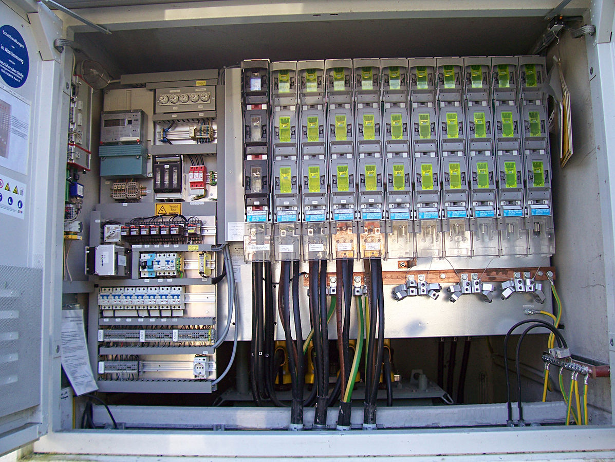
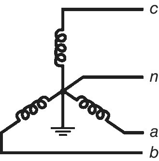
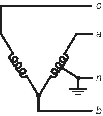
Commercial and industrial low voltage customers in Europe, Australia, and New Zealand are usually provided with a 230/400 V three‐phase supply (three‐phase conductors and the neutral) from an LV transformer arrangement like that in Figure 1.
These customers may, therefore, run single‐phase loads between any phase conductor and neutral, as well as line connected three‐phase loads.
The four‐wire wye (or star) 230/400 V connection is probably the most common low-voltage distribution arrangement, and it is used in many countries worldwide.
Figure 1 Typical 230/400 V three‐phase supply.
In some countries, large commercial or industrial low-voltage loads can also be supplied with a three‐wire 400/690 V supply.
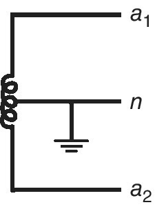
In the USA and Canada, however, residential customers are often supplied with two voltages: 120 V for lighting and low‐current loads and 240 V for larger single‐phase loads, such as water heaters or power tools. These voltages are often generated within the same single‐phase transformer using a center‐tapped winding as shown in Figure 2.
The center tap (or neutral terminal) is earthed (connected to ground potential) and therefore the potentials of the two active conductors are 180° apart, that is, they are symmetrical with respect to the earthed neutral conductor. Such single‐phase transformers are usually relatively small, (<100 kVA) and generally supply fewer than ten residences.
Figure 2 Single‐phase transformer using a center‐tapped winding.
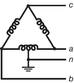
In older parts of North America, other customers are supplied with a three‐phase four‐wire supply from a delta connected secondary winding (Figure 3), where one winding has been fitted with a grounded center tap. This arrangement provides two 120 V supplies for lighting and low‐current loads, while also providing a three‐phase 240 V supply for high‐current loads such as water and space heating.
Because one phase lies 208 V away from the ground while the others are only 120 V from it, this arrangement is known as a high leg delta connection.
Figure 3 Three‐phase four‐wire supply from a delta connected secondary winding.
One advantage of the high leg delta arrangement is that, if necessary, it can be provided in an open delta configuration from two single‐phase transformers rather than three, as shown in Figure 4; however, the maximum three‐phase load that can be applied in this situation is only 1/√3 or 57.7% of the rating with three transformers present.
In other parts of the USA, residential customers are provided with a three‐phase dual‐voltage supply derived from a delta/wye transformer (Δ/Y) with a phase voltage of 120 V and a line voltage of 208 V.
Figure 4 Open delta configuration from two single‐phase transformers.
Commercial and industrial customers in the USA frequently require a three‐phase supply with line voltages greater than either 208 or 240 V; for these a conventional delta/wye (Δ/Y) connected transformer is used, having phase/line voltages of either 265/460 V or 277/480 V.
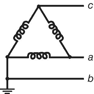
Finally, there is one Low-Voltage winding arrangement that has historically been used in the USA for mainly three‐phase loads, which deserves special comment. It is known as a corner grounded delta, or a grounded b phase system (Figure 5). This configuration is no longer used in new installations but it was used for many years in irrigation and oil pumping applications and is occasionally still in use today.
One advantage of the corner grounded delta is its ability to continue to supply load when operating as an open delta, as described above. This feature provided the possibility of doing maintenance on each single‐phase transformer in turn, from a three‐phase bank, without having to disconnect the entire load.
Today, three‐phase transformers are more reliable and are not assembled from single‐phase devices, and therefore the corner grounded delta has lost its popularity.
Figure 5 Corner grounded delta, or a grounded b phase system.
There are some disadvantages associated with this configuration that should also be mentioned.
Firstly, for reasons of safety, it is necessary to identify the grounded phase at all points along the line.
Secondly, a phase‐to‐ground fault in a corner grounded delta network is essentially a phase‐to‐phase fault, and in 480 V systems quite large fault currents can flow through one pole of the circuit breaker. Interrupting such single‐phase fault currents can be challenging, especially if the circuit breaker chosen does not have a sufficiently high single pole interruption rating.
Many molded case circuit breakers used in Low-Voltage applications have a considerably higher three‐phase fault interruption capacity than a single‐phase one.
A bolted phase‐to‐phase fault (i.e. one with zero impedance) can generate as much as 87% of the current available in a three‐phase fault, and the breaker chosen must be capable of clearing this level of fault current.
Not all molded case circuit breakers have the ability to interrupt single‐phase currents of this magnitude. Circuit breakers used in corner grounded delta networks must, therefore, be carefully chosen with the necessary single pole interruption capacity in mind.
Voltage Tolerance
The Low-Voltage distribution voltage levels mentioned above are all subject to a prescribed tolerance. This is partly because the MV system voltage fluctuates as a function of changes in the reflected LV load.
Although the Medium-Voltage system potential is regulated by the HV/MV transformer (through the use of an on‐load tap‐changer), voltage drops that occur throughout the MV network, as well as within the MV/LV transformer itself, are directly reflected into the LV network since the MV/LV transformer usually does not have on‐load tap‐change facilities, that is, it operates at a fixed transformation ratio.
The International Electro-technical Commission (IEC) standard IEC 60038, entitled ‘Standard Voltages’ defines a ±10% tolerance on the nominal supply voltage for 50 Hz LV systems, and +10% −5% tolerance1 for 60 Hz systems. It also allows a 3% voltage drop for lighting circuits and 5% for all other circuits within a customer’s premises.
Collectively this means that for 50 Hz systems the Utilization Voltage seen at outlets within a customer’s premises may vary from the nominal voltage by +10% −13% for lighting circuits, and +10% −15% for all other circuits.
For 60 Hz systems, the overall tolerance is +10% −8% for lighting circuits and ±10% for all other circuits. Table 1 shows the typical ranges of common Low-Voltage distribution voltages.
Table 1 Typical distribution voltage ranges.
| System Frequency (Hz) |
Nominal Voltage | Highest Supply Or Utilization Voltage | Lowest Supply Voltage | Lowest Utilization Voltage For Lighting | Lowest Utilization Voltage For Other Loads |
| 50 | 230/400 | 253/440 | 207/360 | 200/348 | 196/340 |
| 60 | 120/208 | 127/220 | 109/190 | 106/184 | 104/180 |
| 60 | 230/400 | 253/440 | 219/380 | 212/368 | 207/360 |
(IEC 60038, Copyright © 2009 IEC Geneva, Switzerland. www.iec.ch)
Load Balance
It is important that the total connected load is shared almost equally across all three phases, that is, it is balanced. This is generally achieved in a residential distribution system by ensuring that the number of customers connected to each phase is roughly equal, given that residential loads are generally similar and they also have comparable daily load profiles.
Whether a small commercial or industrial customer’s load is balanced usually depends largely on how well the single‐phase load is distributed, since three‐phase loads, (motors for example) tend to be inherently balanced.
On the other hand, very large industrial customers (base load customers) are required to present a balanced load to the network as part of their connection agreements.
