In this project, you’ll combine what you’ve learned in the previous led projects to create a led bar graph that you can control with a potentiometer.
Create a Dimmer Switch to Control LED Brightness Using Arduino
Control an LED with Push-button Switch and Arduino | Step by Step
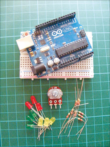
Parts Required
- Arduino board
- Breadboard
- Jumper wires
- 9 LEDs
- 50k-ohm potentiometer
- 9 220-ohm resistors
How It Works
A bar graph is a series of LEDs in a line, similar to what you might see on an audio display. It’s made up of a row of LEDs with an analog input, like a potentiometer or microphone. In this project, you use the analog signal from the potentiometer to control which LEDs are lit. When you turn the potentiometer one way, the LEDs light up one at a time in sequence, as shown in Figure 1-1(a), until they are all on, shown in Figure 1-1(b). When you turn it the other way, they turn off in sequence, as shown in Figure 1-1(c).
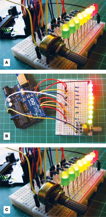
FIGURE 1-1: The LEDs light up and turn off in sequence as you turn the potentiometer.
THE BUILD
1. Insert the LEDs into the breadboard with their shorter, negative legs in the GND rail. Connect this rail to Arduino GND using a jumper wire.
2. Insert a 220-ohm resistor for each LED into the breadboard, with one resistor leg connected to the positive LED leg. Connect the other legs of the resistors to digital pins 2–10 in sequence, as shown in Figure 1-2. It’s important that the resistors bridge the break in the breadboard as shown.
| LEDS | ARDUINO |
| Positive legs | Pins 2–10 via a 220-ohm resistor |
| Negative legs | GND |
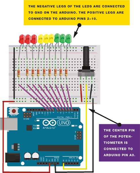
Figure 1-2: Circuit diagram for the bar graph
3. Place the potentiometer in the breadboard and connect the center pin to Arduino A0. Connect the right outer pin to +5V and the left potentiometer pin to GND.
| POTENTIOMETER | ARDUINO |
| Left pin | GND |
| Center pin | A0 |
| Right pin | +5V |
4. Upload the code in “The Sketch” below.
The Sketch
The sketch first reads the input from the potentiometer. It maps the input value to the output range, in this case, nine LEDs. Then it sets up a for loop over the outputs. If the output number of the LED in the series is lower than the mapped input range, the LED turns on; if not, it turns off. See? Simple! If you turn the potentiometer to the right, the LEDs light up in sequence. Turn it to the left, and they turn off in sequence.

