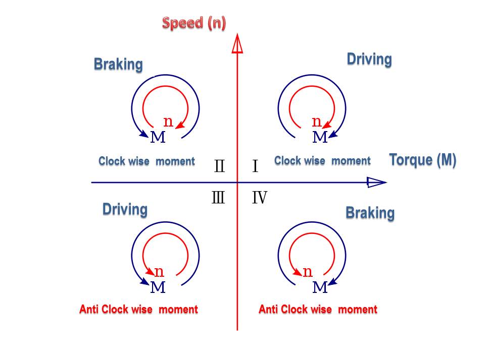
AC motors produce work to drive a load by a rotating shaft. The amount of work produced is a function of the amount of torque produced by the motor shaft and the speed of the shaft. The primary function of all motor drives is to control the speed and torque of a motor.
To safely control a motor, a variable frequency drive must monitor electrical characteristics such as motor current, motor voltage, drive temperature, and other operating conditions. All motor drives are designed to remove power when there is a problem. Some drives allow conditions and faults to be monitored and displayed.
In addition to controlling motor speed and torque, a Variable frequency drive can include additional specialty functions that are built-in, programmed, or sent to the drive through on-board communication with a PC or PLC.
Controlling frequency (in Hz) to an AC motor controls the speed of the motor. Variable frequency drives control frequency applied to a motor over the range 0 Hz to several hundred Hertz.
Variable frequency drives are programmed for a minimum operating speed and a maximum operating speed to prevent damage to a motor or driven load. Damage occurs when a motor is driven faster than its rated nameplate speed. AC motors should not be driven at speeds greater than 2% of the rated nameplate speed.
Volts per Hertz (V/Hz) is the relationship between voltage and frequency that exists in a motor and is expressed as a ratio. Controlling the V/Hz ratio applied to an AC motor controls motor torque.
An AC motor develops rated torque when the V/Hz ratio is maintained. During acceleration (any speed between 1 Hz and 60 Hz), the motor shaft delivers constant torque because the voltage is increased at the same rate as the frequency. Once a Variable frequency drive reaches the point of delivering full motor voltage, increasing the frequency does not increase torque on the motor shaft because voltage cannot be increased further to maintain the V/Hz ratio. See Figure 1.
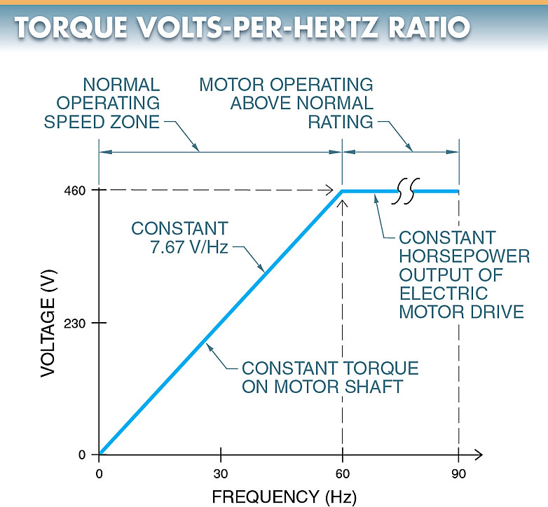
Figure 1. Controlling the volts-per-hertz ratio (V/Hz) applied to an AC motor controls motor torque.
Carrier Frequencies
The carrier frequency is the frequency that controls the number of times solid-state switches in the inverter of a motor drive with pulse width modulation turn on and off.
The higher the carrier frequency, the more individual pulses there are to reproduce the fundamental frequency.
The fundamental frequency is the frequency of the voltage used to control motor speed.
The number of carrier frequency pulses per fundamental frequency is found by applying the following formula:
\[\begin{align}& P=\frac{{{F}_{CARR}}}{{{F}_{FUND}}} \\& where\text{ } \\& P\text{ }=\text{ }pulses\text{ } \\& {{F}_{CARR}}\text{ }=\text{ }carrier\text{ }frequency\text{ } \\& {{F}_{FUND}}\text{ }=\text{ }fundamental\text{ }frequency \\& \\\end{align}\]
The fundamental frequency is the frequency of voltage that a motor uses, but the carrier frequency actually delivers the fundamental frequency voltage to the motor.
The carrier frequency of most motor drives can range from 1 kHz to approximately 16 kHz. A carrier frequency of 6 kHz used to produce a 60 Hz fundamental frequency would have 20 individual pulses per fundamental cycle. See Figure 2. The higher the carrier frequency, the closer the output sine wave is to a pure fundamental frequency sine wave.
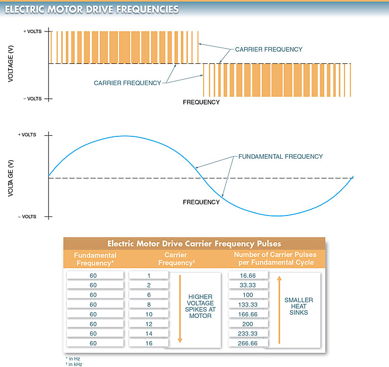
Figure 2. Carrier frequencies of Variable frequency drives range from 1 kHz to 16 kHz.
Motor noise is a problem in motor drive applications, such as in HVAC systems where the noise can carry throughout an entire building. Increasing the frequency to a motor above the standard 60 Hz increases the noise produced by the motor. Noise is noticeable in the 1 kHz to 2 kHz range since it is within the range of human hearing and is amplified by the motor.
A motor connected to a Variable frequency drive delivering a 60 Hz fundamental frequency with a carrier frequency of 2 kHz is approximately three times louder than the same motor connected directly to a pure 60 Hz sine wave with a magnetic motor starter.
Manufacturers have raised the carrier frequency beyond the range of human hearing to eliminate noise. High carrier frequencies cause greater power loss (thermal loss) in a Variable frequency drive due to the solid- state switches in the inverter.
Variable frequency drives should be slightly derated or the size of heat sinks should be increased due to the increase in thermal loss. Derating a motor drive decreases the power rating of the drive. Increasing the heat sink size adds to the cost of the drive. See Figure 3.
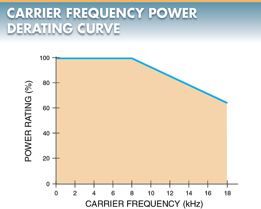
Figure 3. A Variable frequency drive may need to be derated at higher carrier frequencies to protect the insulation of a motor.
Higher carrier frequencies are better than lower carrier frequencies to a certain extent. For example, a 6 kHz to 8 kHz carrier frequency simulates a pure sine wave better than a 1 kHz to 3 kHz carrier frequency and reduces the motor temperature. Since the voltage delivered to the motor better simulates a pure sine wave, less heat is produced. A slight decrease in motor temperature increases insulation life.
Pulse Width Modulation
Pulse width modulation (PWM) is a method of controlling the amount of voltage sent to a motor by converting the DC voltage into fixed values of individual DC pulses.
Variable frequency drives must control the amount of voltage produced in order to control the speed and torque of a motor.
PWM controls the amount of voltage output. The fixed-value pulses are produced by the high-speed switching of transistors, normally insulated-gate bipolar transistors (IGBTs), on and off. By varying the width of each pulse (time ON) and/or by varying the frequency, the voltage can be increased or decreased. The greater the width of individual pulses, the higher the DC voltage output. See Figure 4. PWM of DC voltage is also used to reproduce AC sine waves.
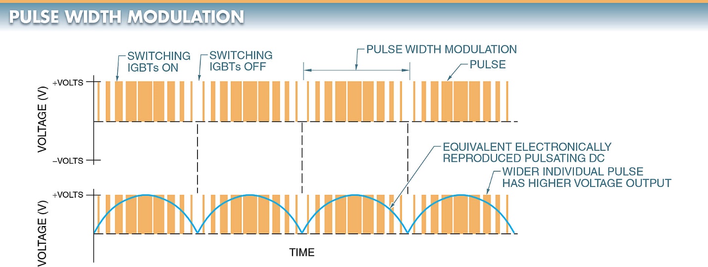
Figure 4. Pulse width modulation is used to produce a pulsating DC output.
When PWM is used with AC voltage, two IGBTs are used for each phase. One IGBT is used to produce positive pulses and another IGBT is used to produce negative pulses of a sine wave. Since AC drives are normally used to control 3φ motors, six IGBTs (two per phase) are used to simulate 3φ power. See Figure 5.
Higher IGBT switching frequencies better simulate AC sine waves than lower frequencies. As simulated AC sine waves become more accurate, motors produce less heat.
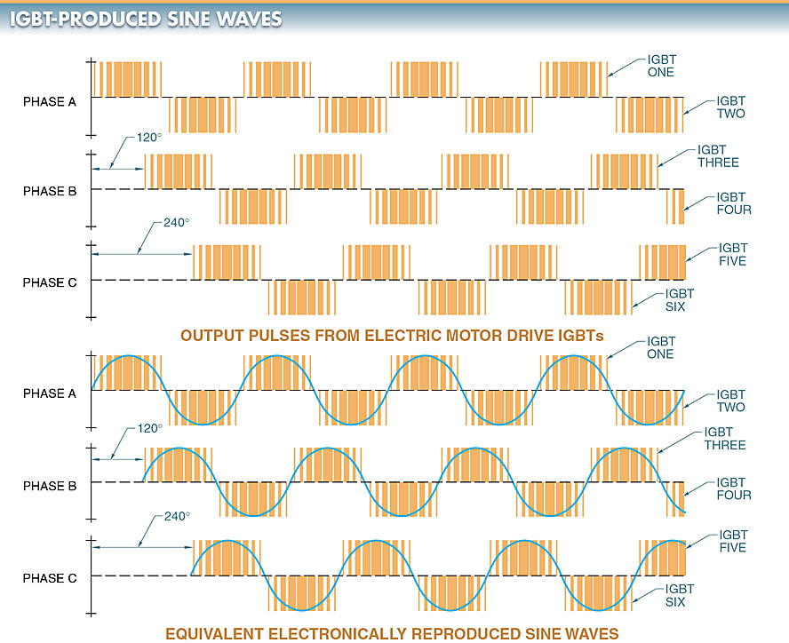
Figure 5. IGBTs with pulse width modulation are used to produce simulated 3φ power.
