The article provides an overview of electromechanical relays, their working principles, and key types including general-purpose, machine control, and reed relays. It highlights their applications, structural differences, and specific features like contact configurations, voltage handling, and operational mechanisms.
An electromechanical relay is a device that controls one electrical circuit by opening and closing contacts in another circuit. Depending on design, relays normally do not control power-consuming devices directly, except for small loads which draw less than 15 A.
Electromechanical Relays have traditionally been used in machine tool control, industrial assembly lines, and commercial equipment. Relays are used to switch starting coils in contactors and motor starters, heating elements, pilot lights, audible alarms, and some small motors (less than 1/8, HP).
A small voltage applied to a relay results in a larger voltage being switched. See Figure 1. For example, applying 24 V to the relay coils may operate a set of contacts that control a 230 V circuit. In this case, the relay acts as an amplifier of the voltage or current in the control circuit because relay coils require a low current or voltage to switch, but can energize larger currents or voltages.
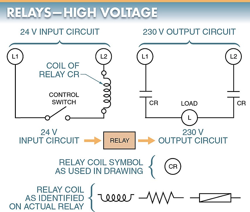
Figure 1. Relays may be compared to amplifiers in that small voltage input results in large voltage output.
Another example of an electromechanical relay providing an amplifying effect is when a single input to the relay results in several other circuits being energized. See Figure 2. An input may be considered amplified because certain mechanical relays provide eight or more sets of contacts controlled from any one input.

Figure 2. Relays may be compared to amplifiers in that a single input may result in multiple outputs.
The two major types of relays are the electromechanical relay and the solid-state relay. An electromechanical relay (EMR) is a switching device that has sets of contacts that are closed by a magnetic effect. A solid-state relay (SSR) is a switching device that has no contacts and switches entirely by electronic means.
Types of electromechanical relays
Electromechanical relays that are common to commercial and industrial applications may be general-purpose, machine control, or reed relays. The major differences between the types of electromechanical relays are their intended use in the circuit, cost, and life expectancy of each device.
General-Purpose Relays
A general-purpose electromechanical relay is a mechanical switch operated by a magnetic coil. See Figure 3. General-purpose relays are available in AC and DC designs. These electromechanical relays are available with coils that can open or close contacts ranging from millivolts to several hundred volts.
Relays with 6 V, 12 V, 24 V, 48 V, 115 V, and 230 V coils are the most common. General-purpose electromechanical relays are available that require as little as 4mA at 5VDC or 22mA at 12VDC.These relays are available in a wide range of switching configurations.
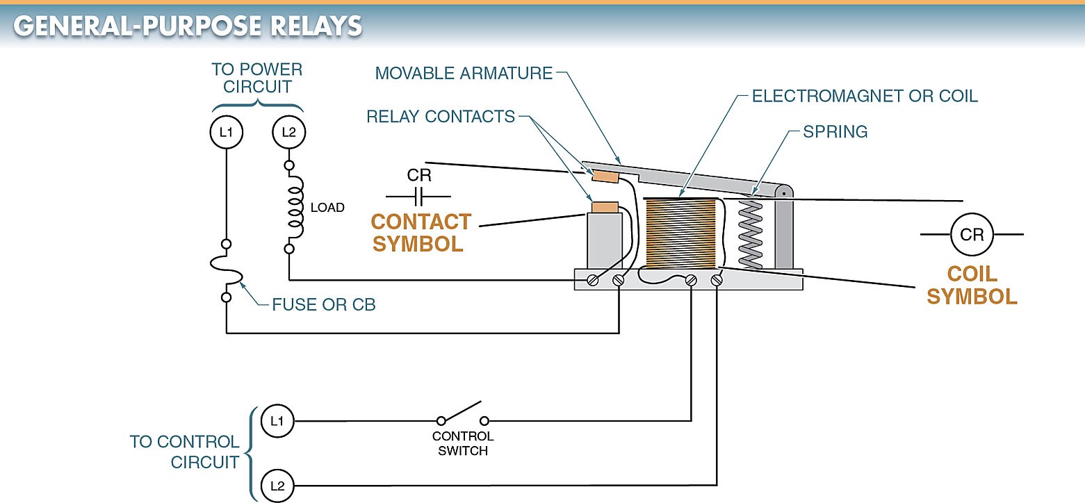
Figure 3. A general-purpose relay is a mechanical switch operated by a magnetic coil.
General-purpose relays are electromechanical relays that include several sets (normally two, three, or four) of non-replaceable NO and NC contacts (normally rated at 5 A to 15 A) that are activated by a coil. See Figure 4.
A general-purpose relay is a good relay for applications that simplify troubleshooting and reduce costs. Special attention must be given to the contact current rating when using general-purpose relays because the contact rating for switching DC is less than the contact rating for switching AC. For example, a 15 A AC-rated contact normally is only rated for 8 A to 10 A DC.
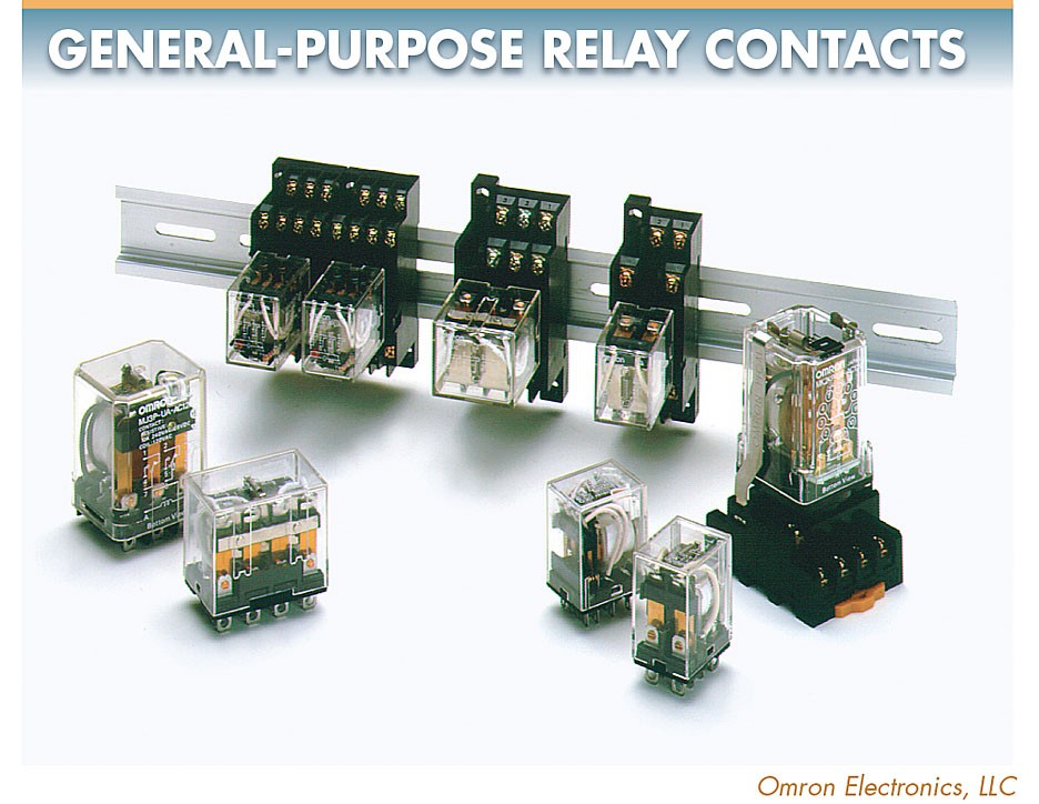
Figure 4. General-purpose relays are electromechanical relays that include several sets of non-replaceable NO and NC contacts that are activated by a coil.
General-purpose electromechanical relays are designed for commercial and industrial applications where the economy and fast replacement are high priorities. Most general-purpose relays have a plug-in feature that makes for quick replacement and simple troubleshooting. Because they are inexpensive, they are thrown away rather than replaced.
Contacts.
Contacts are the conducting part of the relay that acts as a switch to make or break a circuit. The most common contacts are the single-pole, double- throw (SPDT); double-pole, double-throw (DPDT); and the three-pole, double-throw (3PDT) contacts. Relay contacts are described by their number of poles, throws, and breaks. See Figure 5.
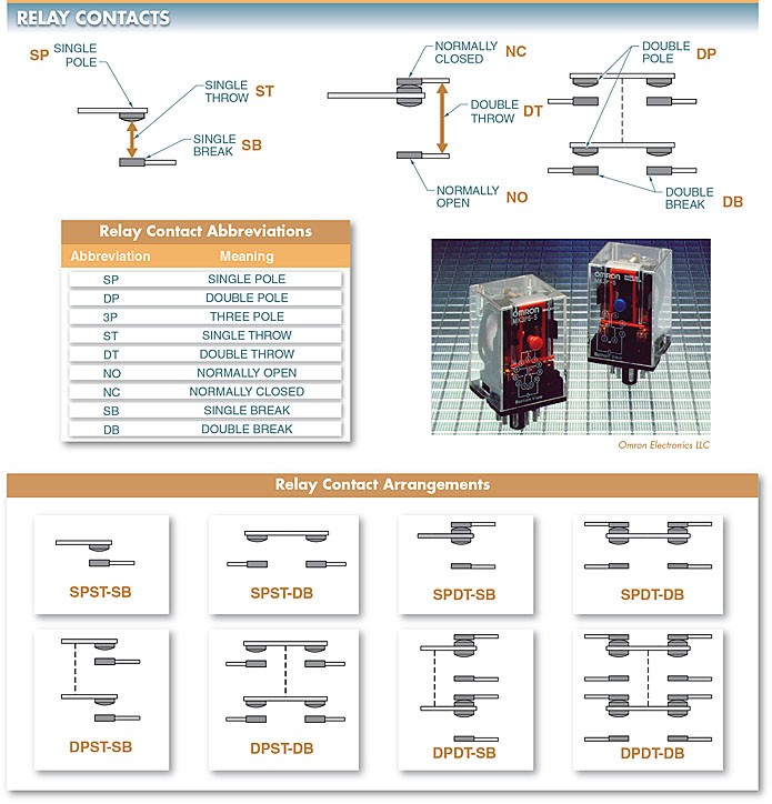
Figure 5. Relay contacts are described by their number of poles, throws, and breaks.
A pole is the number of completely isolated circuits that a relay can switch. A single-pole contact can carry current through only one circuit at a time. A double-pole contact can carry current through two circuits simultaneously.
In a double-pole contact, the two circuits are mechanically connected to open or close simultaneously and are electrically insulated from each other. The mechanical connection is represented by a dashed line connecting the poles. Relays are available with 1 to 12 poles.
A throw is the number of closed contact positions per pole. A single-throw contact can control only one circuit. A double-throw contact can control two circuits.
A break is the number of separate places on a contact that open or close an electrical circuit. For example, a single-break contact breaks an electrical circuit in one place.
A double-break (DB) contact breaks the electrical circuit in two places. All contacts are the single break or double break. Single-break (SB) contacts are normally used when switching low-power devices such as indicating lights. Double-break contacts are used when switching high-power devices such as solenoids.
Tech Tip
A relay contact block may contain more contacts than are required for a particular application. Unused relay contacts can be connected in parallel with the used contacts to divide the current flow over both sets of contacts. Contact life can be extended because dividing the current flow over multiple sets of contacts reduces the current flow through any one set.
Electromechanical Relay manufacturers use a common code to simplify the identification of relays. See Figure 6. This code uses a form letter to indicate the type of electromechanical relay.
For example, Form A has one contact that is NO and closes (makes) when the coil is energized. Form B has one contact that is NC and breaks (opens) when the coil is energized. Form C has one pole that first breaks one contact and then makes a second contact when the coil is energized. Form C is the most common form.
In some electrical applications, the exact order in which each contact operates (makes or breaks) must be known so the circuit can be designed to reduce arcing. Arcing occurs at any electrical contact that has current flowing through it when the contact is opened.

Figure 6. Relay manufacturers use a common code (form letter) to simplify the identification of relays.
Machine Control Relays
A machine control relay is an electromechanical relay that includes several sets (usually two to eight) of NO and NC replaceable contacts (typically rated at 10 A to 20 A) that are activated by a coil. Machine control relays are the backbone of electromechanical control circuitry and are expected to have a long life and a minimal amount of problems.
Machine control electromechanical relays are used extensively in machine tools for direct switching of solenoids, contactors, and starters. See Figure 7. Machine control electromechanical relays provide easy access for contact maintenance and may provide additional features like time delay, latching, and convertible contacts for maximum circuit flexibility.
Convertible contacts are mechanical contacts that can be placed in either a NO or NC position. Machine control relays are also known as heavy-duty or industrial control relays.
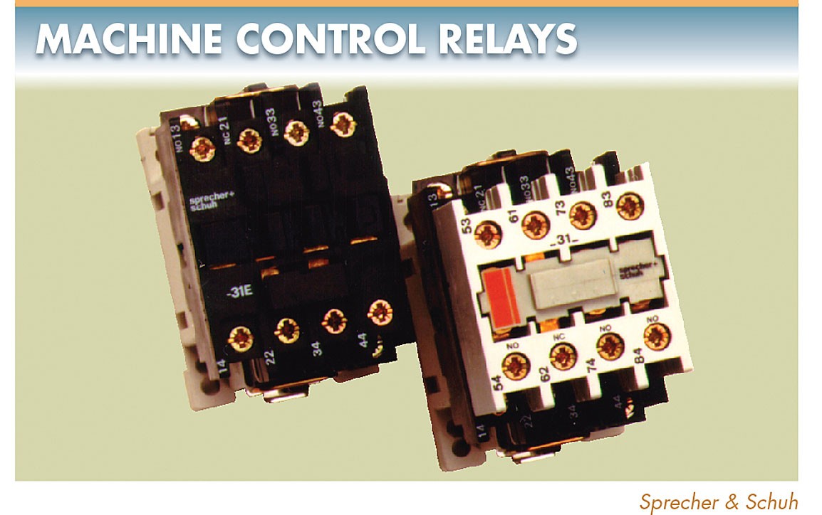
Figure 7. Machine control relays are used extensively in machine tools for direct switching of solenoids, contactors, and starters.
In a machine control electromechanical relay, each contact is a separate removable unit that may be installed to obtain any combination of NO and NC switching. These contacts are also convertible from NO to NC and from NC to NO. See Figure 8.
The unit may be used as either a NO or NC contact by changing the terminal screws and rotating the unit 180°. Relays of 1 to 12 contact poles are readily assembled from stock parts. Machine control relays may have additional decks (groups of contacts) stacked onto the base unit.
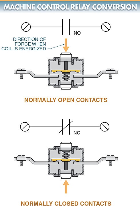
Figure 8. Machine control electromechanical relay contacts are convertible from NO to NC and from NC to NO.
The control coils for machine control relays are easily changed from one control voltage to another and are available in AC or DC standard ratings.
Machine control relays have a large number of accessories that may be added to the relay unit. These include indicating lights, transient suppression, latching controls, and time controls.
Reed Relays
A reed relay is an electromechanical relay which is fast-operating, single-pole, single-throw switch with normally open (NO) contacts hermetically sealed in a glass envelope. See Figure 9.
During the sealing operation, dry nitrogen is forced into the tube, creating a clean inner atmosphere for the contacts. Because the contacts are sealed, they are unaffected by dust, humidity, and fumes. The life expectancy of reed type electromechanical relay contacts is quite long.
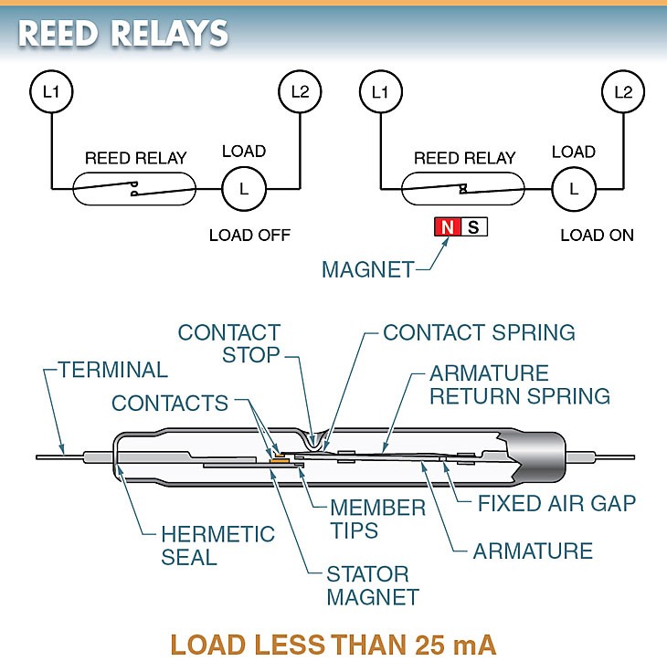
Figure 9. A reed relay is a fast-operating, single-pole, single- throw switch that is activated by a magnetic field.
A reed relay includes a very low current-rated contact (less than 400 mA) that is activated by the presence of a magnetic field. Reed relays may be activated in a variety of ways, which allows them to be used in circuit applications where other electromechanical relay types are inappropriate.
Reed relays are designed to be actuated by an external movable permanent magnet or DC electromagnet. When a magnetic field is brought close to the two reeds, the ferromagnetic (easily magnetized) ends assume opposite the attracting force of the opposing poles overcomes the stiffness of the reed, drawing the contacts together. Removing the magnetizing force allows the contacts to spring open. AC electromagnets are not suitable for reed relays because the reed relay switches so fast that it would energize and de-energize on alternate half-cycles of a standard 60 Hz line.
Reed Contacts.
To obtain a low and consistent contact resistance, the overlapping ends of the contacts may be plated with gold, rhodium, silver alloy, or other low-resistance metal. Contact resistance is often under 0.1 Ω when closed. Reed contacts have an open contact resistance of several million ohms.
Most reed contacts are not directly capable of switching of industrial solenoids, contactors, and motor starters. Reed relay contact ratings indicate the maximum current, voltage, and volt-amps that may be switched by the relay. Under no circumstances should these values be exceeded.
Tech Tip
Reed relays are operated by a magnetic field. Unshielded relays (the least expensive type) that are placed close to each other can cause false relay operation. Shielded relays should be used when the relays must be located near each other or when magnetic fields from motors and transformers may cause false operation.
Reed Relay Actuation.
A permanent magnet is the most common actuator for a reed relay. Permanent- magnet actuation can be arranged in several ways depending on the switching requirement. One of the most commonly used arrangements is proximity motion.
The proximity motion arrangement uses the presence of a magnetic field that is brought within a specific proximity (close distance) to the reed relay to close the contacts. The distance for activating any given electromechanical relay depends on the sensitivity of the relay and the strength of the magnet.
A more sensitive relay or stronger magnet needs less distance for actuation. Methods of proximity motion operation are the pivoted motion, perpendicular motion, parallel motion, and front-to-back motion. See Figure 10. In each method, either the magnet or relay is moved.
In some applications, both the magnet and relay are in motion. The contacts operate quickly, with the snap action and little wear. The application and switching requirements determine the best method.
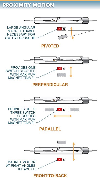
Figure 10. The proximity motion arrangement uses the presence of a magnetic field brought within a specific proximity to the reed relay to close the contacts.
Types of Electromechanical Relays Key Takeaways
Electromechanical relays play a vital role in various electrical and electronic applications due to their ability to control large voltages and currents with relatively low input signals. Their design flexibility—ranging from general-purpose to machine control and reed relays—enables them to meet the diverse needs of industrial automation, machine tools, and precision control systems. These relays not only act as amplifiers by enabling a small signal to switch larger loads, but also offer versatility through different contact configurations and additional features such as convertible contacts and time-delay options.