A transformer (Figure 1) is a magnetically-operated device or machine that can change values of voltage, current, or impedance in a given electrical circuit without any change in frequency. In comparison to the many types of electrical utilization equipment used in the world today, transformers are the most efficient machines known. Worst-case efficiencies are normally 90% or better, with the best-case efficiencies approaching 99%. Transformers can be divided into three classifications: auto, current, and isolation.
Due to the lack of any moving parts, transformers are AC circuit devices. The process of induction, which is required for their magnetic operation, depends on a length of conductor and a concentrated electromagnetic field with relative motion between the two. The ever-changing and periodically-reversing alternating current of both the primary and secondary circuits of the transformer provides the relative motion. Varying-amplitude DC can also be transformed through a transformer; there just will not be any change in current polarity (reversal in the direction of current flow).
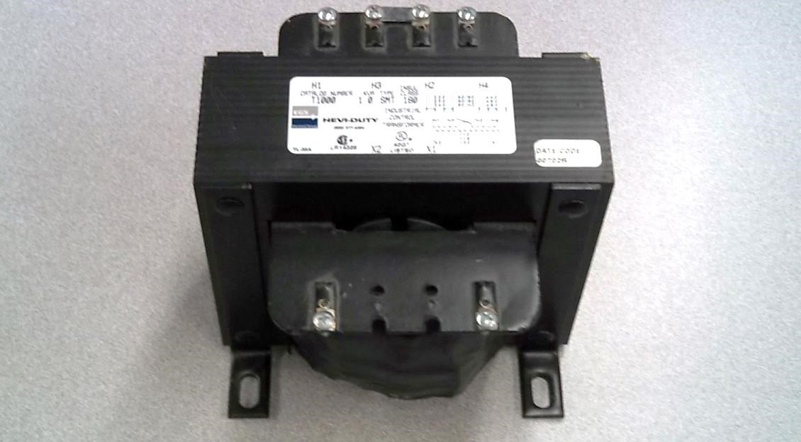
Figure 1. A transformer is a magnetically-operated device or machine
Transformer Applications
The transformer can be used as a means to isolate one part of an AC electrical power distribution system from another. It is used to change from one system voltage rating to another, to boost the circuit voltage when it’s too low, and to buck the circuit voltage when it’s too high. Finally, the transformer due to its own internal impedance provides an effective means of reducing the magnitude of available fault overcurrent at different locations within a given AC electrical-power power distribution system.
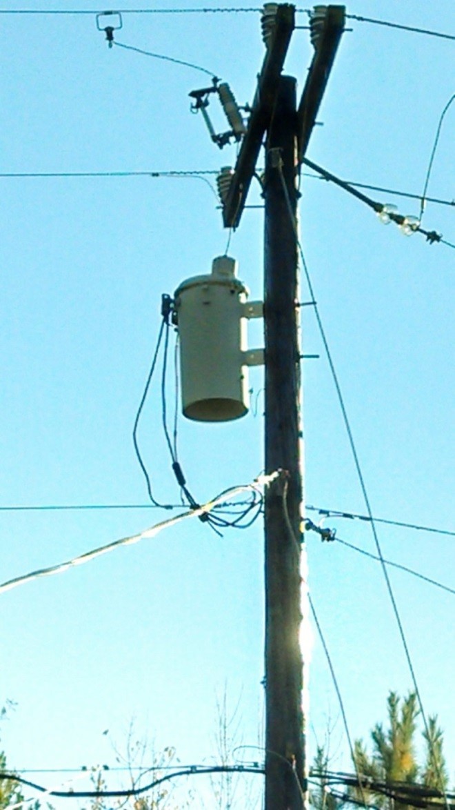
Figure 2. A single-phase step-down distribution service point transformer
At the load end of the cross-country transmission lines in the electric utility company’s parallel grid, transformers are used to step down the voltage and step up the current (Figure 2). As stated in the introduction to this module, this step-down transformer is normally used as the service point of the AC electrical power supply to the building or other structure. The secondary of the transformer supplies the service conductors for entry into the building or other structure. In addition to isolating the building or other structure service and AC electrical power distribution system from the utility-grid AC electrical power distribution system, this load-end transformer also limits the amount of available fault overcurrent (short-circuit or ground-fault overcurrent) that can be delivered to the secondary service conductors. (The utility grid is considered to be an infinite source in terms of the magnitude of available fault overcurrent.)
In addition to the service-supply transformer, other transformers can be supplied from the service or feeder circuit within the AC electrical power distribution system of the building or other structure, which is often a large switchgear or unit substation, to step down (even further) the magnitude of available fault overcurrent to a connected load, such as a secondary panel, a motor-control center, or other type of load center.
The amount of fault overcurrent available at the load terminals of a switchgear — either short-circuit or ground-fault overcurrent — is determined by the length of the service conductors between the connection to the electric utility source (load-end transformer) and the unit substation within the building or other structure; the impedance rating of the contained transformer (within the unit substation), and the load-current rating of the secondary switchgear. When a secondary load center is located in the immediate vicinity of the switchgear, the available fault overcurrent, which is already limited by the unit substation transformer (as compared to the infinite fault overcurrent available from the electric-utility bus), can still be relatively high due to the short conductor length.
The impedance of a second isolation transformer, which includes both the primary winding resistance, the inductive load resistance of the iron core, and the secondary winding resistance, can be used to limit the available fault overcurrent within the interrupting rating (operating limits) of the fuses or circuit breaker protecting the load circuit and connected electrical utilization equipment.
For signaling, remote control, or other low-power, low-voltage control or sensing circuits, additional, even higher impedance-rated control (signaling) transformers are used to limit the rated-load current of the transformer primary circuit to a value well below the load-current rating of the supply branch-circuit fuse(s) or circuit breaker.
Principle of Transformation
When the line wires in the cross-country transmission of electrical power or the circuit conductors within a building or other structure electrical-power distribution system conduct sinusoidal alternating current, a varying electromagnetic field, which is also sinusoidal, is generated perpendicular to and all along the overall length of the line wires or other circuit conductors.
If another line wire or circuit conductor, which can be mechanically and electrically isolated and insulated from the line wire or circuit conductor conveying the alternating current, is immersed in the line wire or circuit conductor’s associated sinusoidal electromagnetic field, the principle of induction causes a voltage to be induced in the second circuit conductor. The relative motion between the electromagnetic field and this second conductor is provided by the sinusoidal electromagnetic field itself: This is referred to as transformer action.
As shown in Figure 3, the simplest construction of a transformer consists of two separate coils of wire (windings) wrapped around a common iron core. When an AC voltage is applied to the primary winding (coil) of the transformer, a concentrated, alternating electromagnetic field is generated in the iron core by the flow of alternating current through the winding. The generated electromagnetic field causes an alternating voltage to be induced in the secondary coil (winding). If a load is connected to the secondary winding, current is caused to flow: Hence the voltage and current of the primary supply circuit have been transformed.
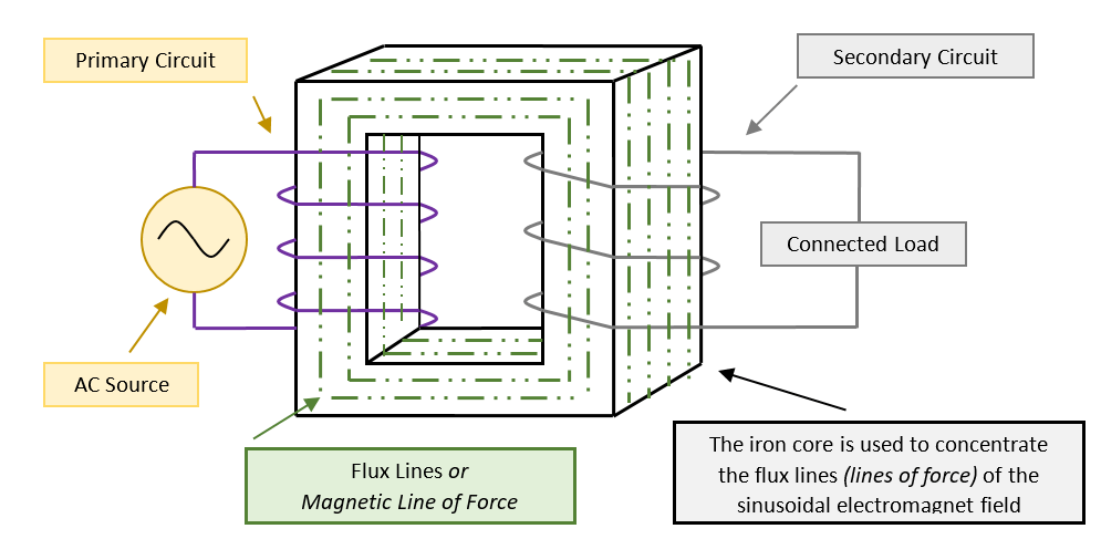
Figure 3. Functional operation of a single-phase isolation transformer
Technically, magnetic lines of force, commonly referred to as magnetic flux lines, form a concentric pattern around the outer surface of the conductor, which fans out perpendicular to and along the overall length of the conductor. The concentric flux lines are located side-by-side along the total length of the primary circuit. The heaviest concentration of flux lines along the length of the conductor is in the center, closest to the surface of the conductor. As the flux lines fan out from the surface of the conductor, the air offers high resistance (reluctance) to the flow of the flux lines, diminishing the strength of the electromagnetic field.
Wrapping the length of the respective circuit conductors in a spiral coil tends to concentrate the number of flux lines around the body of the coil. The number of flux lines at any cross-section along the surface of the coil increases as flux lines from adjacent wraps add to concentrate or intensify the electromagnetic field as it travels across the surface, perpendicular to the parallel run of the conductors.
When the coil of wire is fitted over an iron core, the electromagnetic field is further concentrated in the iron core, which serves as a good conductor of the magnetic flux lines. A better core construction would envelop the windings as much as possible in an iron container to create multiple, complete magnetic flux paths.
The core of the coil (winding in a transformer) does not have to be constructed of iron or other ferrous metal for transformer action to take place. In communication or other amplifier circuits operating at higher frequencies, the core of the transformer may be constructed of a hollow tube made of cardboard: This would be referred to as an air-core transformer. For signaling, control, or power transformers, the iron core provides a low resistance magnetic field path for better coupling (power transfer) of the two circuits.
The primary circuit of the transformer is the source of electrical power for both the transformer and its connected load. The secondary circuit of the transformer is the supply circuit (or power supply) for the connected load (from the transformer). In the primary circuit, the coil of wire creates an inductive load that restricts the flow of primary current. Looking at the primary circuit only, the single coil of wire with an AC source serves as a reactor, which, except for wire resistance (heat losses), can only store the electrical energy. The main restriction of primary-circuit current is reflected impedance from the secondary circuit of the transformer.
The greatest restriction (highest value of impedance) reflected in the primary circuit will occur when the secondary circuit is open (no connected load). If the transformer were ideal, without secondary-circuit current flow, there should be no primary-circuit current flow. But, no transformer is ideal: a low-value of primary-circuit current flows with the secondary circuit open. This open-secondary primary-circuit current is referred to as the transformer’s excitation current.
Excitation current supports the continual reversal of the magnetic-pole polarities (core losses, dissipated as heat). As the sinusoidal waveform produced by the alternator (generator of the AC power) periodically reverses the direction of current flow along the length of the primary winding, the flux lines in the concentrated electromagnetic field of the iron core of the transformer are also caused to reverse their direction of flow, such that the poles of the created magnet (electromagnet) in the iron core are continually changing from north to south, south to north, and north to south in sinusoidal fashion.
The iron core is also a good conductor of electricity. If the iron core is a solid cast of iron, the relative motion of the sinusoidal electromagnetic field will cause stray currents to flow at random across the iron core (perpendicular in reference to the direction of flow of the magnetic flux lines). These stray currents, referred to as eddy currents, cannot be channeled either in or out of the core structure to do useful work: Instead, their presence creates additional heat in the core structure. The effect of eddy currents is reduced to a bare-bones minimum by constructing the iron core of individual thin sheets of steel that are allowed to oxidize before being assembled as the iron core. The oxidation serves as an insulator to the flow of eddy currents. Riveting several of these oxidized sheets together (laminated), assembles the iron core to form the required cross-section of the flux path.
The excitation current contributes to the energy expended due to eddy-current losses and to the continual de-magnetization and re-magnetization of the iron core (field reversal-the resulting molecular friction in the iron is referred to as hysteresis). The expended electrical energy of the excitation current is referred to as iron core losses in the transformer, which are normally dissipated as heat (I2R losses).
The primary excitation current is constant from the no-load to the full-load range of the transformer rating, as well as when the transformer is electrically overloaded. For power transformers, the excitation current is of such low value when compared to the secondary full-load current rating that the excitation current and transformer losses are ignored: The power rating for the transformer is considered the same for the primary and secondary circuits. Without a connected load (complete path), voltage is available from the secondary leads or terminals of the transformer, but secondary current in an open circuit cannot flow — again the greatest value of reflected impedance.
The least restriction (lowest value of impedance) reflected in the primary circuit of the transformer will occur when the two ends of the secondary winding are shorted together. In essence, the transformer becomes its own electrical load: The restriction to secondary current flow is limited only to the resistance of the wire that makes up the secondary winding and the magnetic losses of the iron core.
Short-circuit current (secondary shorted) is referred to as fault overcurrent: “When the transformer circuit is put in a fault condition, the flow of high-magnitude overcurrent generates excessive heat in the conductors, which can cause the conductor insulation to fail. The associated electromagnetic field of the fault overcurrent also puts mechanical stress on the conductors, especially at their terminations, and the framing of the iron core. The stress comes from the motor action (inductive reaction — the two opposing electromagnetic fields pushing away from each other) between the conductors and the metal enclosures that protect the conductors.
Circuit Connections of Isolation Transformers
Transformer circuits are normally drawn using standard symbols. The introductory transformer circuit of Figure 3 is redrawn in Figure 4, using the standard symbols for a transformer circuit: The two parallel bars (lines) between the two winding symbols indicate a transformer with an iron core. The two open circles in the indicated circuit conductors represent either wire terminals on some sort of terminal block or short sections of wire called “field leads”, which are the ends of the windings within the transformer. Because a single terminal block or the entire field leads of both transformer circuits (primary and secondary) are contained in the single terminal housing, the winding leads have to be identified to distinguish the higher-voltage winding leads from the lower-voltage winding leads. The respective circuit windings have to be further identified to distinguish between the beginning and ending of a particular winding.
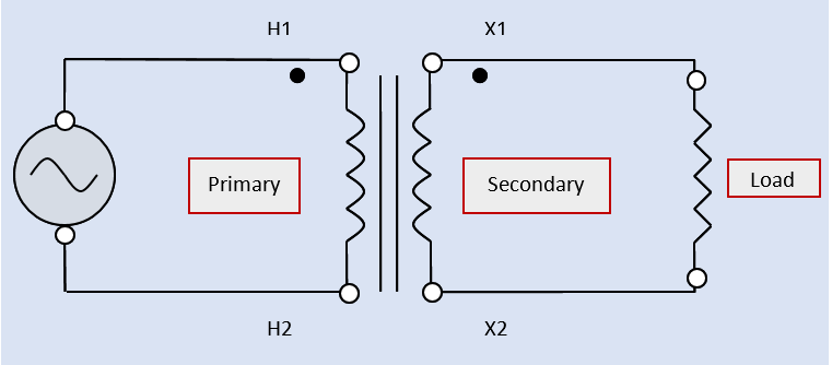
Figure 4. Diagram using standard electrical symbols to show the AC supply, a single-phase transformer, and its connected load in an electrical schematic
The capital letter H is used to identify the higher-voltage winding leads. The capital letter X is used to identify the lower-voltage winding leads. The “in” (beginning or start) field lead of either circuit winding is identified with the number 1. The “out” (ending or finish) field lead of the same winding is identified with the number 2. The leads or terminals identified as H1 and H2 are the in-and-out connections of the higher-voltage winding. The leads or terminals identified as X1 and X2 are the in-and-out connections of the lower-voltage winding.
It seems reasonable that if the capital letter H is used to identify the high-voltage winding leads that the capital letter L would be used to identify the low-voltage winding leads. But the capital letter L is already used in electrical drawings to identify the different ungrounded line conductors (phase conductors — L1, L2, and so on) in an AC electrical power distribution system. To avoid confusion, the capital letter X was chosen to identify the crossed-over or transformed lower-voltage winding leads.
If a single-phase AC transformer has two primary windings (a dual winding transformer), the in-lead of the second winding will be identified as H3, and the out-lead will be identified as H4. If the single-phase AC transformer also has two lower-voltage windings, the in-and-out leads of the second winding will be identified (respectively) as X3 and X4. Traditionally the in-leads will always be identified with odd numbers and out-leads will always be identified with even numbers. The in-and-out leads of a single winding are always two consecutive numbers, odd then even.
The numbers also help to identify the polarity of the transformer windings. The two solid dots, adjacent to the H1 and X1 terminals in Figure 4, are used in establishing the polarity of the two windings. As drawn, H1 and X1 are in-phase. As shown in Figure 5, alternating current is sinusoidal: One alternation is positive in reference to a zero-volt baseline. The second alternation is negative in reference to the same zero-volt baseline. The solid dots in Figure 4 indicate that X1 in the secondary circuit will go positive when H1 in the primary circuit goes positive and negative when H1 goes negative.
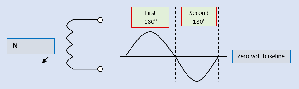
Figure 5. Generation of a single-phase 2-wire AC sine waveform electrical supply from a rotating magnetic field
For boost or buck transformations (the voltage is boosted up in value, or bucked down in value), or for correct polarity in a 3-phase AC bank formation (delta or wye configuration), the dots ensure that the transformer leads will be interconnected correctly. More about this as the different transformer connections are introduced and discussed.
All transformers are initially rated as single-phase with the minimum construction of one primary two-wire winding (connected to the AC power source) and one secondary two-wire winding (supplying the connected load). When the primary and secondary leads of three single-phase AC transformers are interconnected (respectively) in either a delta or a wye configuration, a 3-phase AC transformer bank is created to transform the 3-phase AC power. When the respective circuit windings of three single-phase AC transformers are mounted on a common iron frame (iron core), the assembly is referred to as a 3-phase AC transformer.
The transformer with power supply and connected load shown in Figure 3 and represented by standard symbols in Figure 4 represents an isolation (or conventional) transformer: the secondary winding is physically and electrically isolated from the primary winding. The transformation of voltage, current, or circuit impedance is by mutual induction between the two inductive circuits.
