The article covers the concepts of impedance and admittance in AC circuit, explaining the phasor representation of resistors, capacitors, and inductors, and how to calculate their impedances. It also discusses how to combine these components to find equivalent impedance and the role of admittance as the inverse of impedance in circuit analysis.
The i -v relationships of resistors, capacitors, and inductors can be expressed in phasor notation. As phasors, each i-v relationship takes the form of a generalized Ohm’s law:
$\text{V=IZ}$
where the phasor quantity Z is known as impedance. For a resistor, inductor, and capacitor, the impedances are, respectively:
$\begin{matrix}{{Z}_{R}}=R & {{Z}_{L}}=j\omega L & {{Z}_{C}}=\frac{1}{j\omega C} \\\end{matrix}=\frac{-j}{\omega C}$
Combinations of resistors, inductors, and capacitance can be represented by a single equivalent impedance of the form:
\[\begin{matrix}Z\left( j\omega \right)=R\left( j\omega \right)+jX\left( j\omega \right) & {} & \text{units of }\!\!\Omega\!\!\text{ (ohms)} \\\end{matrix}\]
Where R (jω) and X (jω) are known as the “resistance” and “reactance” portions, respectively, of the equivalent impedance Z. Both terms are, in general, functions of frequency ω.
The admittance is defined as the inverse of impedance.
$\begin{matrix}\text{Y=}\frac{\text{1}}{\text{Z}} & {} & \text{units of S }\left( Siemens \right) \\\end{matrix}$
Consequently, all the DC circuit relations and techniques introduced in Chapter 3 can be extended to AC circuits. Thus, it is not necessary to learn new techniques and formulas to solve AC circuits; it is only necessary to learn to use the same techniques and formulas with phasors.
Generalized Ohm’s Law
The impedance concept reflects the fact that capacitors and inductors act as frequency- dependent resistors. Figure 1 depicts a generic AC circuit with a sinusoidal voltage source VS phasor and an impedance load Z, which is also a phasor and represents the effect of a generic network of resistors, capacitors, and inductors.
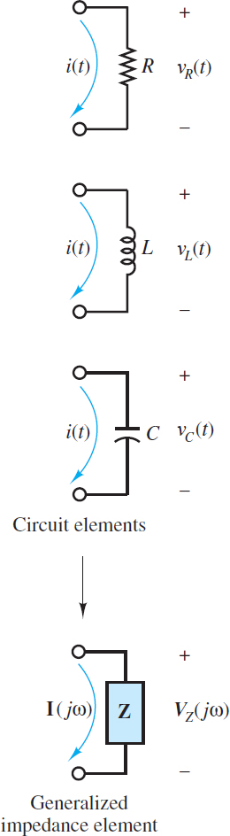
Figure 1 The impedance concept
The resulting current I is a phasor determined by:
$\begin{matrix}\operatorname{V}=IZ & Generalized\text{ }Ohms\text{ }Law~ & \left( 1 \right) \\\end{matrix}$
A specific expression for the impedance Z is found for each specific network of resistors, capacitors, and inductors attached to the source. To determine Z it is first necessary to determine the impedance of resistors, capacitors, and inductors using:
$\begin{matrix}\text{Z=}\frac{\text{V}}{\text{I}} & Definition\text{ }of\text{ }impedance & \left( 2 \right) \\\end{matrix}$
Once the impedance of each resistor, capacitor, and inductor in a network is known, they can be combined in series and parallel (using the usual rules for resistors) to form an equivalent impedance “seen” by the source.
Impedance of a Resistor
The i-v relationship for a resistor is, of course, Ohm’s law, which in the case of sinusoidal sources is written as (see Figure 2):

Figure 2 For a resistor, VR(t)=iR(t)R
$\begin{matrix}{{v}_{R}}(t)={{i}_{R}}\left( t \right)R & {} & \left( 3 \right) \\\end{matrix}$
or, in phasor form,
\[{{\text{V}}_{\text{R}}}{{e}^{j\omega t}}={{\text{I}}_{\text{R}}}{{e}^{j\omega t}}R\]
Where ${{V}_{R}}={{V}_{\operatorname{R}}}{{e}^{j\theta t}}$ and ${{I}_{R}}={{I}_{\operatorname{R}}}{{e}^{j\theta t}}$ are phasors.
Both sides of the above equation can be divided by ejωt to yield:
$\begin{matrix}{{\text{V}}_{\text{R}}}\text{=}{{\text{I}}_{\text{R}}}R & {} & \left( 4 \right) \\\end{matrix}$
The impedance of a resistor is then determined from the definition of impedance:
$\begin{matrix}{{\text{Z}}_{\text{R}}}=\frac{{{\text{V}}_{\text{R}}}}{{{\text{I}}_{\text{R}}}}=R & {} & \left( 5 \right) \\\end{matrix}$
Thus:
ZR = R Impedance of a resistor
The impedance of a resistor is a real number; that is, it has a magnitude R and a zero phase, as shown in Figure 2. The phase of the impedance is equal to the phase difference between the voltage across an element and the current through the same element.
In the case of a resistor, the voltage is completely in phase with the current, which means that there is no time delay or time shift between the voltage waveform and the current waveform in the time domain.
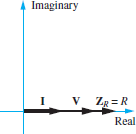
Figure 2 Phasor diagram of the impedance of a resistor. Remember that Z=V/L
It is important to keep in mind that the phasor voltages and currents in AC circuits are functions of frequency, V = V (jω) and I = I (jω). This fact is crucial for determining the impedance of capacitors and inductors, as shown below.
Impedance of an Inductor
The i-v relationship for an inductor is (see Figure 3):
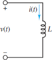
Figure 3 For an inductor
\[\begin{matrix}{{v}_{L}}\left( t \right)=L\frac{d{{i}_{L}}\left( t \right)}{dt} & {} & \left( 6 \right) \\\end{matrix}\]
At this point, it is important to proceed carefully. The time-domain expression for the current through the inductor is:
\[\begin{matrix}{{i}_{L}}\left( t \right)={{I}_{L}}\cos \left( \omega t+\theta \right) & {} & \left( 7 \right) \\\end{matrix}\]
Such that
\[\begin{align}& \frac{d}{dt}{{i}_{L}}\left( t \right)=-{{I}_{L}}\omega \sin \left( \omega t+\theta \right) \\& ={{I}_{L}}\omega \cos \left( \omega t+\theta +\pi /2 \right) \\& =\operatorname{Re}({{I}_{L}}\omega {{e}^{j\pi /2}}{{e}^{j\omega t+\theta }}) \\& =\operatorname{Re}\left[ {{I}_{L}}\left( j\omega \right){{e}^{j\omega t+\theta }} \right] \\\end{align}\]
Notice that the net effect of the time derivative is to produce an extra ( j ω) term along with the complex exponential expression of iL(t). That is:
| Time Domain | Frequency Domain |
| ${}^{d}/{}_{dt}$ | $j\omega $ |
Therefore, the phasor equivalent of the i-v relationship for an inductor is:
$\begin{matrix}{{\text{V}}_{\text{L}}}=L\left( j\omega \right){{I}_{L}} & {} & \left( 8 \right) \\\end{matrix}$
The impedance of an inductor is then determined from the definition of impedance:
$\begin{matrix}{{\text{Z}}_{\text{L}}}=\frac{{{\text{V}}_{\text{L}}}}{{{\text{I}}_{\text{L}}}}=j\omega L & {} & \left( 9 \right) \\\end{matrix}$
Thus:
$\begin{matrix}{{Z}_{L}}=j\omega L=\omega L\angle \frac{\pi }{2} & ~Impedance\text{ }of\text{ }an\text{ }inductor~ & \left( 10 \right) \\\end{matrix}$
The impedance of an inductor is a positive, purely imaginary number; that is, it has a magnitude of ωL and a phase of π/2 radians or 90◦, as shown in Figure 4. As before, the phase of the impedance is equal to the phase difference between the voltage across an element and the current through the same element.
In the case of an inductor, the voltage leads the current by π/2 radians, which means that a feature (e.g., a zero crossing point) of the voltage waveform occurs T /4 seconds earlier than the same feature of the current waveform. T is the common period.
Note that the inductor behaves as a complex frequency-dependent resistor and that its magnitude ωL is proportional to the angular frequency ω. Thus, an inductor will “impede” current flow in proportion to the frequency of the source signal. At low frequencies, an inductor acts like a short-circuit; at high frequencies, it acts like an open-circuit.
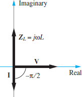
Figure 4 Phasor diagram of the impedance of an inductor. Remember that Z=V/L
Impedance of a Capacitor
The principle of duality suggests that the procedure to derive the impedance of a capacitor should be a mirror image of the procedure shown above for an inductor. The i-v relationship for a capacitor is (see Figure 5):
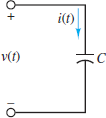
Figure 5 For a capacitor
\[\begin{matrix}{{i}_{C}}\left( t \right)=C\frac{d{{v}_{C}}\left( t \right)}{dt} & {} & \left( 11 \right) \\\end{matrix}\]
The time-domain expression for the voltage across the capacitor is:
\[\begin{matrix}{{v}_{C}}\left( t \right)={{V}_{C}}\cos \left( \omega t+\theta \right) & {} & \left( 12 \right) \\\end{matrix}\]
Such that
\[\begin{align}& \frac{d}{dt}{{v}_{C}}\left( t \right)=-{{V}_{C}}\omega \sin \left( \omega t+\theta \right) \\& ={{V}_{C}}\omega \cos \left( \omega t+\theta +\pi /2 \right) \\& =\operatorname{Re}({{V}_{C}}\omega {{e}^{j\pi /2}}{{e}^{j\omega t+\theta }}) \\& =\operatorname{Re}\left[ {{V}_{C}}\left( j\omega \right){{e}^{j\omega t+\theta }} \right] \\\end{align}\]
Notice that the net effect of the time derivative is to produce an extra ( j ω) term along with the complex exponential expression of vC(t). Therefore, the phasor equivalent of the i-v relationship for a capacitor is:
$\begin{matrix}{{\text{I}}_{\text{C}}}=C\left( j\omega \right){{\text{V}}_{\text{C}}} & {} & \left( 13 \right) \\\end{matrix}$
The impedance of an inductor is then determined from the definition of impedance:
\[\begin{matrix}{{\text{Z}}_{\text{C}}}=\frac{{{\text{V}}_{\text{C}}}}{{{\text{I}}_{\text{C}}}}=\frac{1}{j\omega C}=\frac{-j}{\omega C} & {} & \left( 14 \right) \\\end{matrix}\]
Thus:
\[\begin{matrix}{{Z}_{C}}=\frac{1}{j\omega C}=\frac{-j}{\omega C}=\frac{1}{\omega C}\angle -\frac{\pi }{2} & {} & \left( 15 \right) \\\end{matrix}\]
The impedance of a capacitor is a negative, purely imaginary number; that is, it has a magnitude of 1/ωC and a phase of −π/2 radians or −90o, as shown in Figure 6. As before, the phase of the impedance is equal to the phase difference between the voltage across an element and the current through the same element. In the case of a capacitor, the voltage lags the current by π/2 radians, which means that a feature (e.g., a zero-crossing point) of the voltage waveform occurs T/4 seconds later than the same feature of the current waveform. T is the common period of each waveform.
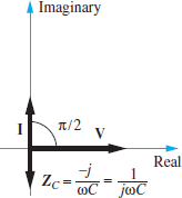
Figure 6 Phasor diagram of the impedance of a capacitor. Remember that Z=V/L
Note that the capacitor also behaves as a complex frequency-dependent resistor, except that its magnitude 1/ωC is inversely proportional to the angular frequency ω.
Thus, a capacitor will “impede” current flow in inverse proportion to the frequency of the source. At low frequencies, a capacitor acts like an open-circuit; at high frequencies, it acts like a short-circuit.
Generalized Impedance
The impedance concept is very useful in solving AC circuit analysis problems. It allows network theorems developed for DC circuits to be applied to AC circuits. The only difference is that complex arithmetic, rather than scalar arithmetic, must be employed to find the equivalent impedance.
Figure 7 depicts ZR(jω), ZL(jω), and ZC(jω) in the complex plane. It is important to emphasize that although the impedance of resistors is purely real and the impedance of capacitors and inductors is purely imaginary, the equivalent impedance seen by a source in an arbitrary circuit can be complex.
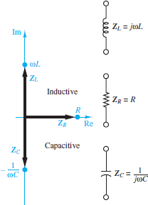
Figure 7 The impedance of R, L and C are shown in the complex plane. Impedances in the upper right quadrant are inductive while those in the lower right quadrant are capacitive.
$\begin{matrix}\text{Z}\left( j\omega \right)=R+X\left( j\omega \right) & {} & \left( 16 \right) \\\end{matrix}$
Here, R is resistance and X is reactance. The unit of R, X, and Z is the ohm.
Admittance
It was suggested that the solution of certain circuit analysis problems was handled more easily in terms of conductance’s than resistances. This is true, for example, when one is using node analysis, or in circuits with many parallel elements, since conductance in parallel add as resistors in series do. In AC circuit analysis, an analogous quantity may be defined—the reciprocal of complex impedance. Just as conductance G was defined as the inverse of resistance, admittance Y is defined as the inverse of impedance:
$\begin{matrix}Y=\frac{1}{Z} & \text{units of S (Siemens)} & \left( 17 \right) \\\end{matrix}$
Whenever the impedance Z is purely real, the admittance Y is identical to the conductance G. In general, however, Y is complex.
$\begin{matrix}\text{Y}=G+jB & {} & (18) \\\end{matrix}$
where G is the AC conductance and B is the susceptance, which is analogous to reactance. Clearly, G and B are related to R and X; however, the relationship is not a simple inverse. If Z = R + jX , then the admittance is:
$\begin{matrix}Y=\frac{1}{Z}=\frac{1}{R+jX} & {} & \left( 19 \right) \\\end{matrix}$
Multiply the numerator and denominator by the complex conjugate Z ̄ = R − jX:
$\begin{matrix}Y=\frac{\overline{Z}}{\overline{Z}Z}=\frac{R-jX}{{{R}^{2}}+{{X}^{2}}} & {} & \left( 20 \right) \\\end{matrix}$
and conclude that
$\begin{align}& \begin{matrix}G=\frac{R}{{{R}^{2}}+{{X}^{2}}} & {} & \left( 21 \right) \\\end{matrix} \\& B=\frac{-X}{{{R}^{2}}+{{X}^{2}}} \\\end{align}$
Notice in particular that G is not the reciprocal of R in the general case!
Resistance and Impedance in an AC Circuit Key Takeaways
Understanding impedance and admittance is essential for the effective analysis and design of AC circuit. Impedance provides a comprehensive framework for combining the effects of resistors, capacitors, and inductors, all of which exhibit frequency-dependent behaviors. By using phasor notation, impedance simplifies the complex relationships in AC circuit into manageable calculations, enabling engineers to apply familiar DC circuit techniques. Admittance, being the inverse of impedance, plays a crucial role in circuit analysis by facilitating the analysis of current flow. These concepts are pivotal in the design of filters, amplifiers, and other electronic systems, where precise control of voltage, current, and frequency characteristics is required.