The transfer of electrical power within the electrical-utility power transmission/distribution grid is normally at high voltage (high tension) to reduce the transmission losses (line losses) along the miles of cable that must be installed between the generating plants and the many cities, commercial and industrial sites, and suburban, as well as rural dwelling communities.
To take advantage of the air’s ability to insulate, most high-voltage lines are run as bare wires (cables)along either steel towers or wood or concrete poles. Because the majority of load current in an AC circuit is forced to flow along the surface of the conductors, rubber or plastic insulation adds to the resistance of a conductor along its length.
Bare conductors of an alternating current run above ground are a natural draw to lightning. To minimize the disturbance of lightning on the electrical power transmission/distribution grid, the supply transformer of the transmission/distribution lines is referenced to earth ground.
As shown in Figure 1, most electrical-utility power transmission/distribution grids originate in a 3-phase AC, 4-wire wye configuration with the common termination of one end of the three single-phase AC windings in the secondary of the supply alternator (at the generating station — not shown) or transformer referenced to earth ground through a driven metal rod grounding-electrode system — normally several metal rods are driven and connected together.
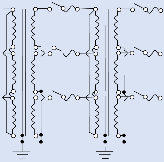
Figure 1. The static ground wire in the 3-phase electrical utility power transmission/distribution grid
The ungrounded electrical-utility transmission/distribution conductors are fused as they leave the supply alternator or transformer. A 4th-wire, non-fused, non-switched static ground-wire, which is connected to the common connection of the three single-phase AC transformer windings with the grounding-electrode conductor(s), is run as a static ground along the top of the steel towers.
Connected as the 4th-wire common to the supply-transformer 3-phase AC, 4-wire secondary, this is not an unbalanced load-return current-carrying neutral conductor because the primary of the load transformer (at the other end of this section of the electrical-utility transmission/distribution system) is connected as a 3-phase AC, 3-wire delta — there is no lower voltage, single-phase AC loads.
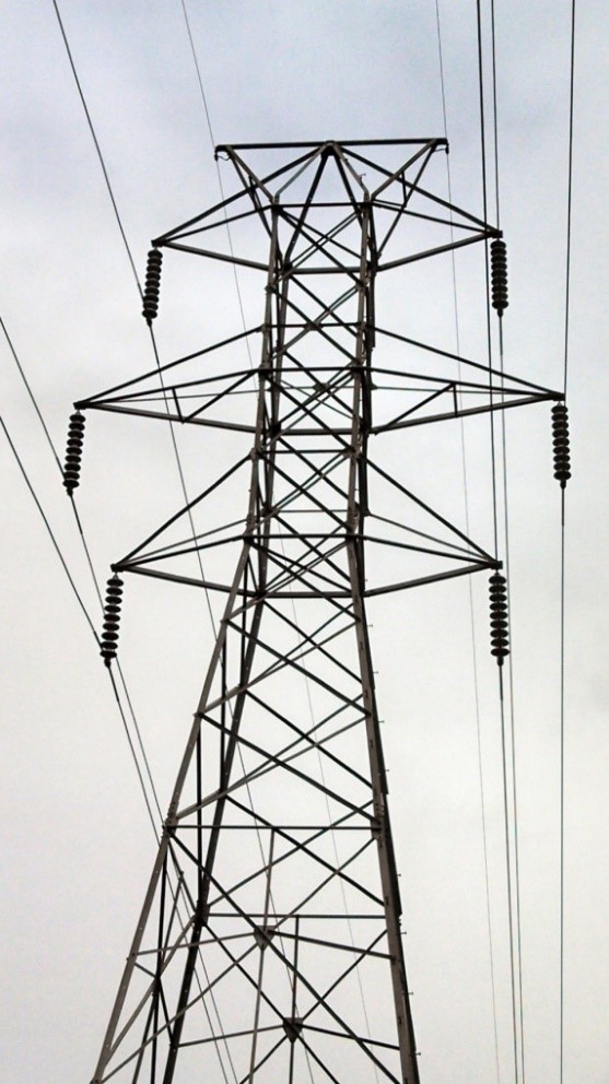
Figure 2. Run along the top of the steel towers, the static ground-wire serves as a type of lightning arrester
Run along the top of the steel towers as shown in Figure 2, the static ground-wire serves as a type of lightning arrester for any lightning drawn to the transmission/distribution lines by the transfer of the AC power. (The ever-changing strength of the electromagnetic field generated around the transmission lines by the conveyance of the alternating current changes the dielectric strength of the air about the transmission/distribution lines).
Technically, because of the redundant grounding at the many steel towers (The foundations of the steel towers serve as redundant grounding-electrode systems along the length of this static ground-wire.), the static ground-wire would aid in lightning dissipation without the secondary of the supply transformer being grounded: But interconnected with the 4th-wire static ground and the multiple grounding-electrode systems, the grounded transformer secondary common affords some crucial benefits to an electrical-utility power transmission/distribution system:
- It will limit the voltage imposed on the ungrounded transmission/distribution conductors by lightning, which occurs when nature’s electrical generating plant is discharged.
- It will limit the voltage imposed on the transmission/distribution conductors by line surges, which normally occur with load shifts or momentary failures or opens on the electric utility power transmission/ distribution grid.
- It will limit the voltage imposed on the transmission/distribution lines by high-tension (higher-voltage) crossover, which occurs when one of the higher-voltage transmission/distribution lines in one of the transformer circuits (either primary or secondary, according to whether the transformer is wired in step-up or step-down voltage configuration) accidentally come in contact with one of the lower-voltage utility transmission/distribution lines of the other transformer (supply or load) circuit.
- It will serve as a ground-fault overcurrent return path should any of the ungrounded transmission/ distribution lines (primary or secondary) come in contact with the transformer’s iron core, metal enclosure, or other non-current-carrying metal parts in the vicinity of the transformer, provided these parts are interconnected with the transformer’s grounding-electrode system.
Run atop the steel towers (again; Figure 2), the static ground wire discharges most of the lightning strikes [(1) in the list], but some of the lightning strikes also hit the ungrounded transmission/distribution lines.
By the grounding of the secondary common, the rated voltage of the single-phase AC windings in the secondary of the supply transformer sets the maximum operating voltage of the ungrounded transmission/distribution lines in reference to earth ground such that the energy of the lightning strike is bled off at a controlled rate (through the affected transformer winding) to minimize the voltage spike that a lightning strike can generate on the electrical-utility power transmission/distribution system.
All the generating stations within an electrical-utility power transmission/distribution grid are technically wired in parallel on the supply side of the grid, which is the primary of the supply transformer back in Figure 1: All the connected loads on the load side of the electrical-utility power transmission/distribution grid are also wired in parallel.
If a large electrical load is turned off due to the opening of an OCPD or if the load is shut off or transferred from one part of the grid to another part of the grid, the mass of electrical power that was being conveyed to that load actually bounces back along the transmission/distribution lines from the open as a standing wave of power; normally referred to as a line surge [(2) in the list].
The line surge (standing wave of power) will be consumed or absorbed by the loads that are still connected to the grid. As with the lightning strike, the common connection of the single-phase AC windings in the supply transformer’s secondary serves as a voltage regulator to bleed off the line surge and minimize the electrical-power disturbance.
The transmission/distribution lines are terminated to a second 3-phase AC load transformer (again; Figure 1) whose primary is configured in a 3-phase AC, 3-wire delta — no lower-voltage, single-phase AC loads. The 4th-wire static ground, extended from the secondary 3-phase AC, 4-wire wye of the supply transformer is terminated to the iron core and the metal case or other enclosure housing the load transformer for ground-fault overcurrent return should one of the ungrounded transmission lines come in contact with any of these noncurrent-carrying metal surfaces.
Once commercial power is generated, several transformers must be wired in series with the electrical-utility power transmission/distribution lines: Initially, a 3-phase AC transformer, with a 3-wire delta primary and a 4-wire wye secondary is used to step up the generating voltage to a higher transmission/distribution line voltage.
As the line losses along the transmission/distribution lines take their toll, another 3-phase AC, the delta-to-wye transformer must be installed to step-up (or boost) the electrical-utility power transmission/distribution line voltage back up to the desired transmission/distribution level. According to the length of the transmission/distribution lines, several of these boost transformers may be required for the electrical-utility power transmission/distribution.
At the consumer end (load end), several other 3-phase AC, delta-to-wye transformers are used to step down (or buck) the higher transmission/distribution voltages to medium-voltage transmission/distribution voltages (transcending from the high steel towers to the lower-height concrete or wooden poles).
The purpose of a transformer is to raise or lower line voltages at the same frequency. Due to the physical construction of the transformers, the primary terminal connections and the secondary terminal connections — operating at different voltages — are in close proximity to each other.
The three ungrounded electrical-utility power transmission/distribution lines are fused as they leave the secondary of the supply transformer to protect them against overcurrent. The 4th-wire static ground of both the primary and secondary circuits at each transformer (supply at one end and load at the other end) are interconnected by a common connection to the respective transformer iron cores, the metal enclosures, and the grounding-electrode system established at each transformer location.
If due to physical damage in a storm or failure of the metal wire, one of the ungrounded higher-voltage electrical-utility power transmission/distribution lines comes in contact with one of the ungrounded lower-voltage transmission/distribution lines at a given transformer location, this would constitute a high-voltage crossover [high-tension crossover — (3) in the list]: The low-value impedance of the lower-voltage, single-phase AC winding in the affected transformer would appear as a short-circuit to the higher-voltage winding in the other transformer and open the line fuse. This same protection is realized with this type of grounded system in either the step-up configuration on the supply (or line) side of the electrical utility power transmission/distribution grid or the step-down configuration on the load side.
Ground-fault current is a high-magnitude, destructive overcurrent that involves at least one ungrounded circuit conductor and the non-current-carrying metal parts of an electrical-utility power transmission/distribution system.
When an equipment-grounding system is established with the static ground wires of both the primary and secondary circuits of the 3-phase AC electrical utility transformers, accidental contact of a primary-circuit transmission / distribution line with the equipment-grounding system on a given 3-phase AC load transformer will, through the fault-return of the static ground-wire, place a short-circuit on the affected secondary single-phase AC winding of the supply transformer and open the affected fuse — disabling the fault condition.
If the ground-fault is due to accidental contact of an ungrounded transmission/distribution line in the secondary of the load transformer — after the fuse, the low-value of impedance created by the point of contact of the ground fault will place a short circuit on the affected secondary single-phase AC winding of the load transformer and open the protective fuse — disabling the fault condition.
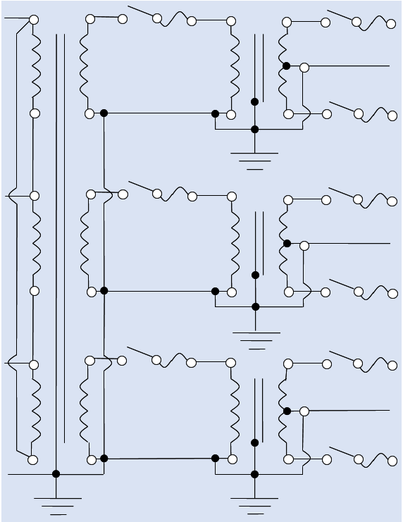
Figure 3. The electrical utility power transmission/distribution system for a rural trunk line grid
If the ground-fault is due to accidental contact of an ungrounded (line) conductor in the secondary of the load transformer — before the fuse, the low-value impedance created by the point of contact of the ground fault will place a short circuit on the affected secondary single-phase AC winding of the load transformer, which will be reflected as a low-value of impedance into the affected transformer primary single-phase AC winding and open the affected fuse at the supply transformer — disabling the fault condition.
This same type of electrical power distribution system — a 3-phase AC, 3-wire delta primary and a 3-phase AC, 4-wire wye secondary referenced to earth ground — is used for the electrical power distribution systems in most commercial or industrial buildings or other structures for the same reasons discussed here for the electrical-utility power transmission/distribution system.
The power consumed in the average dwelling or small commercial business does not warrant 3-phase AC power as just described. Most of the services for these types of structures are rated as single-phase AC, 3-wire at 120/240 volts. As shown in Figure 3, the medium-voltage trunk line of the electrical-utility power transmission/distribution grid that supplies these single-phase AC services (normally 7200 volts to ground) is also single-phase AC. At a common dispersion point on the grid, a 3-phase AC, 3-wire delta to 4-wire wye transformer is installed to establish three single-phase AC 2-wire trunk lines.
The 4th-wire in the 3-phase AC, 3-wire delta primary is a static ground-wire — not part of the load circuit; whereas, the grounded conductor in each single-phase AC 2-wire secondary circuit serves the dual role of an unbalanced load-return conductor and a ground-fault return conductor.
The 4th-wire in the 3-phase AC wye transformer secondary is normally rated at 12,470 volts line-to-line, and 7200 volts line-to-ground (line-to-the 4th-wire common neutral conductor, which is grounded). Three grounded conductors are connected to the common of the secondary 3-phase AC, 4-wire wye to form the three single-phase AC, 2-wire trunk lines: One of the fused, ungrounded, supply phase (single-phase AC) conductors are run with an individual grounded-return conductor in each trunk line.
Instead of just a static ground-wire, the grounded-return conductor of each 2-wire trunk line is a circuit conductor that carries load current — the return of the load current supplied by the ungrounded conductor in a given trunk line: both are connected to the single high-voltage winding of the single-phase AC service transformer primary to complete the primary circuit.
The secondary of each single-phase AC transformer consists of two 120-volt windings wired in series with the interconnection forming a midpoint that is referenced to earth ground through another grounding-electrode system located at the transformer (normally an 8-foot driven metal rod). The other two ends of the two 120-volt windings are the ungrounded service conductors: each operates at 120 volts in reference to ground, which is the 3rd–wire grounded common-return neutral conductor in the set of service conductors extended to the dwelling or small-commercial structure.
Loads connected between the two ungrounded service conductors will operate at 240 volts: wired in series, the voltages of the two windings add to the higher voltage.
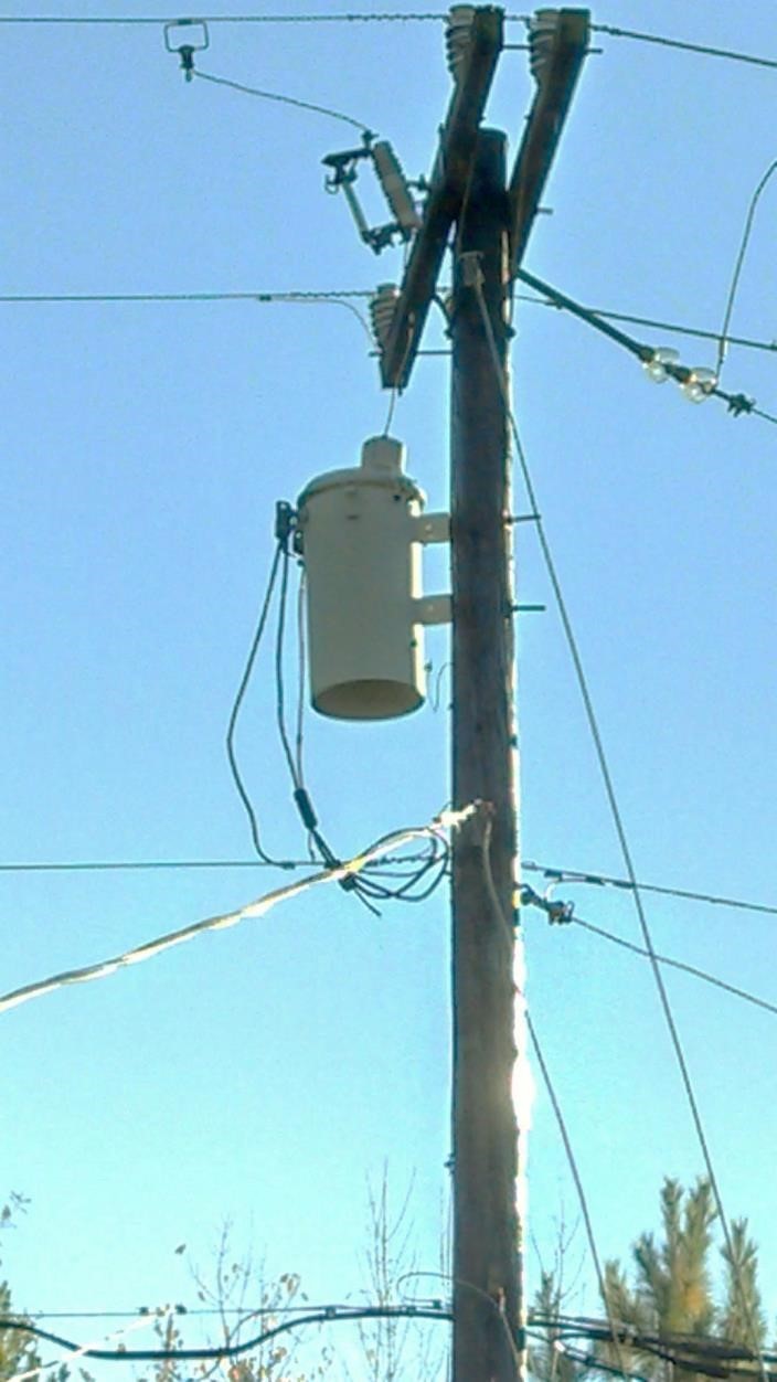
Figure 4. Because the grounded side of the single-phase AC, 2-wire trunk line is a current-carrying conductor that is intentionally grounded, it is connected as the lowest utility conductor on the power pole
Because both the primary and secondary circuits are grounded AC electrical power distribution systems, the grounded conductors of both systems are connected to the metal enclosure (can or case) of the service transformer, which is connected to a grounding-electrode system. Internally bolted to the metal enclosure, the iron core of the transformer is also grounded and interconnected to both systems for ground-fault protection.
The interconnection of the grounded side of the single-phase AC, 2-wire trunk line and the single-phase AC, 3-wire service supply to the dwelling or other structure, provides the same crucial benefits cited at the start of this section for the 3-phase AC electrical-utility power distribution systems: It will limit the voltage imposed on the ungrounded transmission/distribution conductors by lightning, line surges, or high-tension (higher-voltage) crossover, and serve as a ground-fault return path should any of the ungrounded circuit conductors (primary or secondary) come in contact with the transformer’s iron core, metal enclosure, or other non-current-carrying metal parts in the vicinity of the transformer that are interconnected with the transformer’s grounding-electrode system.
Because the grounded side of the single-phase AC, 2-wire trunk line and the common-return grounded neutral conductor in the single-phase AC, 3-wire service supply to the dwelling or another structure is a current-carrying conductor that is intentionally grounded, the grounded side of the single-phase AC, 2-wire trunk line is connected as the lowest utility conductor on the power pole. The ungrounded utility conductors in Figure 4 are connected to glass insulators on the top of the cross arm at the top of the utility pole.
