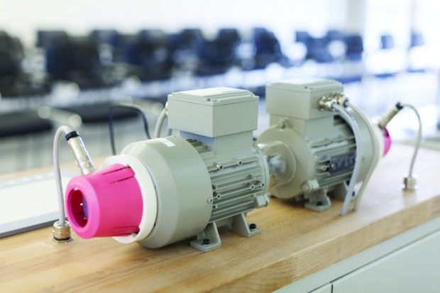
As shown in Figure 1, the installations and uses of electric motors are just as diversified as the many different kinds and horsepower ratings of electric motors. In general, electric motors or electrical utilization equipment that contains motor loads must be provided with a disconnecting means, supply conductors, and some type of overcurrent protection. Either a multi-outlet or an individual branch circuit, with the individual branch circuit for integral-horsepower electric motors being the more common, can supply electric motors.
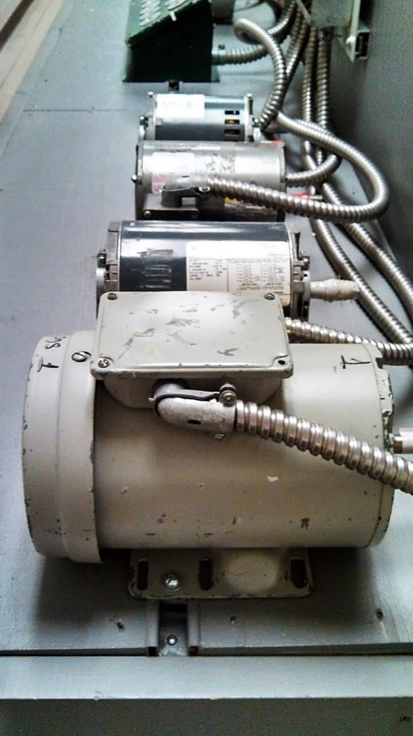
Figure 1. The installations and uses of electric motors are just as diversified as the many different types of electric motors
Any electrical circuit consists of three basic components: a power supply, a connected load, and the circuit conductors that connect the two. The amount of current that will flow from the power supply to the connected load is governed by the magnitude of the applied voltage, the number of phases in the supply (when AC), and the magnitude of the load resistance, or in AC circuits: the load impedance.
Because the circuit conductors are connected in series with the electrical utilization-equipment load, the wire resistance of the conductors further impedes the circuit current. Sized correctly, according to their rated ampacity and the prevailing environmental conditions of operation, the conductor resistance is considered to be negligible. The load impedance is considered to be the circuit impedance.
For a resistive load, such as the heating elements in a storage-type water heater, or the tungsten-filament in an incandescent lamp, the load resistance is fixed at the point of manufacture. The rated full-load current is drawn every time the load is turned on (power is applied).
The impedance of an electric motor is governed by both its manufactured operating characteristics and the inertia or other resistance (by the connected mechanical load) to the turning motion of its rotor.
The electric motor’s impedance is induced in the stator windings by the electromagnetic field of the turning rotor windings [the counter-voltage or CEMF (counter-electromotive force)], and therefore its load current can vary from almost infinite impedance and near zero amps when operated in a no-load condition (drive train disconnected from the rotor driveshaft), to a very low value of circuit impedance and as much as six times its rated-load current (eight times for Design B electric motors) when the electric motor is either started or is operating in a full-load condition and suddenly becomes mechanically overloaded to the point of stalling.
When electric motor stalls, it is forced into a locked-rotor condition. The value or amount of line current drawn by the electric motor falls between these two extremes (near zero amps and six or even more times its rated-load current) according to the torque requirements of the connected mechanical load.
When an electric motor draws current in excess of its full- or rated-load current as specified on the motor nameplate, the motor is said to be in running overload. Overcurrent due to a mechanical overload of an electric motor will cause the supply-circuit and motor-winding conductors to overheat.
Extensive overheating will cause the conductor insulation to fail, which will cause the overcurrent condition to escalate from an overload to a fault overcurrent condition. High-magnitude fault overcurrent, whether short-circuit or ground-fault overcurrent, will normally destroy both the circuit conductors and the windings of the electric motor if not stopped almost instantly.
The size or load rating of the branch-circuit overcurrent protection device for the electric motor circuit must be low enough in value to provide adequate fault protection (short-circuit or ground-fault overcurrent protection), but high enough in value to allow the electric motor to operate with varying load conditions from no load to full load, and in some applications to a certain amount or degree of running overload, yet protect the circuit conductors from extensive overheating.
The full-load current rating listed on a given electric motor nameplate (NP FLC) is the current the motor will draw when operated at its rated voltage, rated frequency (AC motors), and rated torque (horsepower rating). In an AC induction motor, the slip between the synchronous speed of the rotating electromagnetic field created within the confines of the stator assembly, and the actual running (turning) speed of the electromagnetic field induced in the rotor windings is the power supply (voltage source) for the rotor windings.
The amount of or “%-slip” is governed by the torque requirements of the mechanical load driven by the electric motor. At no-load, the %-slip approaches zero — the turning speed of the rotor assembly approaches the synchronous speed of the stator’s rotating electromagnetic field. At zero %-slip — no voltage is induced in the rotor windings; without voltage — no current is induced in the rotor windings; without current — no electromagnetic field is induced in the rotor windings, and; without a counter-electromagnetic field reflected into the rotating stator electromagnetic field — no torque is available from the turning rotor.
The inertia of the rotor assembly plus windage and bearing losses due to friction on the rotor shaft when the AC induction motor is operated without a connected mechanical load (which serves no useful purpose beyond demonstration of the no-load condition), will cause the rotor to slow down or drop out of synchronization with the stator winding assembly’s rotating electromagnetic field.
The near 0%-slip of the now slower-turning rotor will induce a low-value, low-frequency voltage in the rotor windings, which generates enough current and resulting weak electromagnetic field in the rotor windings to interact with the rotating electromagnetic field of the stator windings to bring the rotor speed back in synchronization, where again: no voltage will be induced in the rotor winding.
The high-frequency of the pulsating yet weak counter-electromagnetic field of the rotor winding turning at the no-load near-synchronous speed induces a high-value of counter voltage in the stator windings. The higher value of counter voltage increases the stator winding reactance, which limits the stator winding current to a near-zero value. A 3-phase AC induction motor is almost a purely inductive load when running at no-load speed.
Adding mechanical load causes the turning rotor of the electric motor to slow down. The loss in rotor speed increases the voltage induced in the rotor windings. The increase in voltage increases the current induced in the rotor windings. The increase in current intensifies the strength of the electromagnetic field of the rotor windings, and the increase in strength of this counter-electromagnetic field applies added torque to the connected load-preventing any further slowdown of the rotor. The rotor speed is maintained for the higher value of torque required. This process will continue as a more mechanical load is added until the rotor speed reaches the pull-out or break over (breakdown) torque value of the electric motor.
The pull-out or breakdown torque of an AC induction motor occurs at about 20% slip. At this slower speed of the turning rotor, the interaction of the two revolving electromagnetic fields has diminished to the point that the attraction of the unlike magnetic poles and the repulsion of the like magnetic poles, cannot sustain the torque requirements of the connected (driven) mechanical load. The electric motor and driven load abruptly stop — the motor enters a locked-rotor condition. The impedance of the stator winding assembly returns to the low-value winding resistance. The reduction in the stator-circuit impedance will increase the stator winding current up to the maximum overload condition, which is typically 600% of the AC induction motor’s running full-load current.
When an AC induction motor is initially started under a full-load or an NE Code-allowed mechanical overload condition, until the rotor starts turning, the startup current of the electric motor is equal to the locked-rotor current rating of the motor. Once the rotor begins turning, the counter-voltage (counter-electromotive force or CEMF) induced in the stator windings begins to increase. The stator-circuit current — due to the increase in the stator winding impedance — begins to decrease.
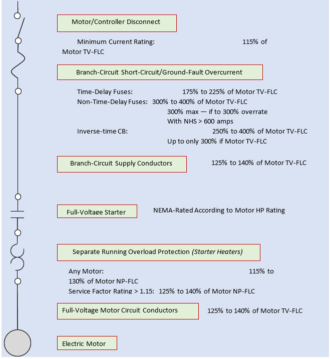
Figure 2. Single-motor branch-circuit summary
Once the electric motor and driven mechanical load are running, the actual load current the AC induction motor will draw depends on the torque requirements of the connected mechanical load (normally referred to as just the “connected load”).
Driving a connected load with torque requirements that are less than the motor’s nameplate-rated horsepower; the motor will draw less than the full-load current posted on its nameplate. Driving a connected load with torque requirements equal to the motor’s nameplate-rated horsepower (at rated voltage and frequency); the motor will draw the full-load current as posted on its nameplate. Driving a connected load with torque requirements that are greater than the motor’s nameplate-rated horsepower. The motor will draw more than the full-load current as posted on its nameplate.
For power-factor correction of the AC electrical power distribution system within the building or other structure, AC induction motor circuits are normally designed to allow the motor to operate in a continuous overload condition.
Operated on overload, the electric motor will draw current in excess of nameplate-rated full-load current, which means the motor will operate at an elevated temperature. The magnitude of allowed overload overcurrent and its duration are normally governed by the construction and other operating characteristics of the AC induction motor, which are established at the point of manufacture.
