Definition: An ammeter measures electrical current in a circuit. An ammeter will usually measure in amperes, milliamperes, or microamperes, depending on the scale or design of the instrument.
Ammeter Working
The coil in the meter movement of an ammeter is wound with many turns of fine wire. If a large current is allowed to flow through this coil, the ammeter will quickly burn out.
In order to measure larger currents, a shunt, or alternate path, is provided for current. Most of the current flows through the shunt, leaving only enough current to safely work the meter movement coil.
The shunt is a precision resistor connected in parallel with the meter coil. The use of shunts is illustrated in Figure 1.
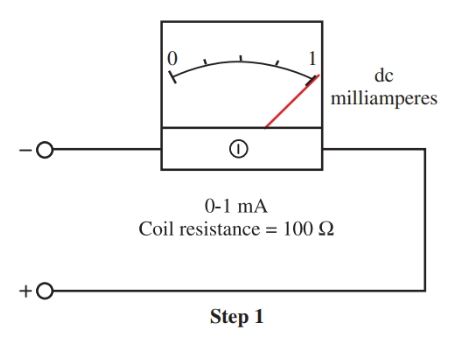
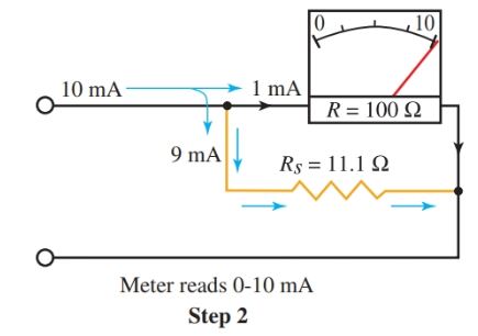
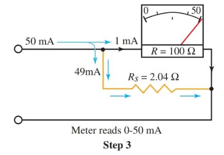
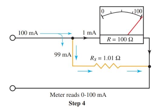
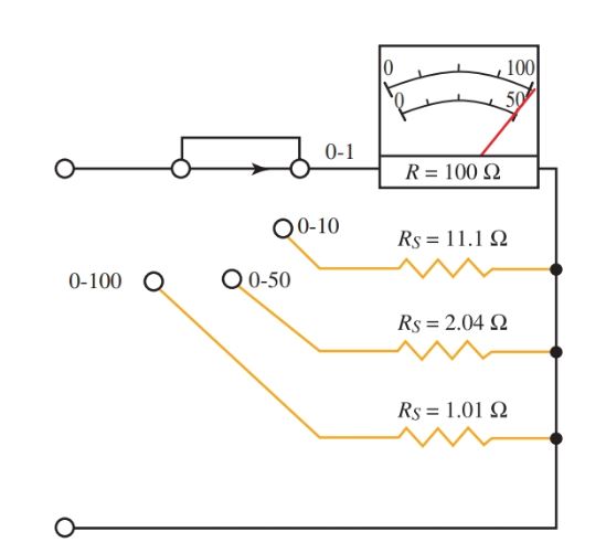
Figure 1.
Step 1—The voltage that causes the full-scale deflection current is computed.
Step 2—The shunt carries 9/10th of the current.
Step 3—The shunt carries 49/50th of the current.
Step 4—The shunt carries 99/100th of the current.
Bottom—Basic setup of an ammeter with three shunt resistors. A switch selects the range.
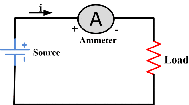
In Figure 2 you see the proper way to connect an ammeter to an electrical circuit. When an ammeter is connected into the circuit, it becomes part of the circuit in order to allow the current to flow through the meter coil.
To connect an ammeter in a circuit, one usually has to make an open by disconnecting some device in the circuit. This allows you to insert the meter into the circuit.
Notice that you are connecting the meter in series with the circuit or device you are trying to measure.
Figure 2. An ammeter is always connected in series with the circuit device being measured. The meter must be connected with proper polarity.
Ammeter Example
The specification of a certain meter movement requires 0.001 A, or one milli-ampere of current, for full-scale deflection of the needle. The ohmic resistance of the meter movement coil is 100 ohms.
Compute the shunt resistor values for a meter that will measure four different ampere ranges. The ranges are as follows: 0–1 mA, 0–10 mA, 0–50 mA, and 0–100 mA.
Step 1.
First, calculate the voltage required for full-scale deflection on the lowest setting which is 0–1 mA.
$\begin{align} & E=I\left( full\text{ }scale\text{ }current \right)\times R\left( resistance\text{ }of\text{ }coil \right) \\ & E=0.001A\times 100 \\ & E=0.1V \\\end{align}$
The meter will read from 0–1 mA without a shunt. For full scale deflection 0.1 volts is required.
Step 2.
To convert this same meter to read from 0–10 mA, a shunt must be connected that will carry 9/10 of the current. Thus, 9 mA of current will travel through the shunt, leaving one milli-ampere to operate the meter.
The first step in the calculation determined that 0.1 V is required for full-scale deflection. The shunt is connected in parallel with the coil, so it will also have 0.1 V applied to it.
Since 0.1 V must be applied across the shunt, and the shunt must also account for 9/10 of the current, you can apply Ohm’s law to calculate the shunt’s resistance.
\[{{R}^{s}}=\frac{E}{I}=\frac{0.1V}{0.009A}=11.1\Omega \]
The meter will require a shunt with a resistance value of 11.1 ohms for the 0–10 mA scale.
Step 3.
To convert this meter for the 0–50 mA scale, a shunt must be used that will carry 49/50 of the current, or 49 mA. The computation is the same as in Step 2.
\[{{R}_{S}}=\frac{0.1V}{0.049A}=2.04\Omega \]
Step 4.
To convert the meter for the 0–100 mA scale, a shunt must be used that will carry 99/100 of the current, or 99 mA.
\[{{R}_{S}}=\frac{0.1V}{0.099A}=1.01\Omega \]
A shunt with an ohmic value of 1.01 is required for the meter to safely use a 0–100 mA range. Look again at Figure 1. Notice the switching device used to change the ranges of the meter. The correct scale on the range dial must be used to correspond to the selected range.
Caution
There are two important things to remember for the safety of your ammeter.
First, an ammeter must always be connected in series with a circuit device or the power supply. Never connect an ammeter in parallel with the power supply or circuit devices, Figure 3.
As you can see through the meter shunt calculations, the applied voltage to the meter movement coil only required 0.1 V for full-scale deflection. If a voltage greater than 0.1 is used, it will cause excessive current to flow through the coil. This will result in damage to the coil.
To make a series connection usually requires breaking the circuit open or disconnecting a device in order to insert the meter. This allows the current to flow through the meter.
The second thing to remember is when the current value you are testing is unknown, start at the highest meter range. This way you will not exceed the highest value on the meter scale during the reading of a circuit.
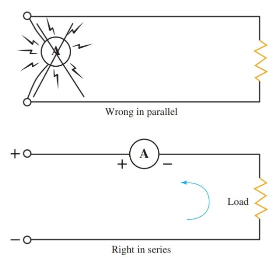
Figure 3. Connecting an ammeter. Top—an incorrect way. Bottom—the correct way.
