Variable Frequency Drive Introduction
This resource is about AC Drives also known as VFDs or Variable Frequency Drives. Modern semiconductors have revolutionized handling the higher power required to run electric motors.
Variable Frequency Drive is a technology where the rotational speed of an electric motor is controlled or varied electronically.
Electric motors were invented in the early 1800’s. These first electric motors ran off of DC (Direct Current) because that was the only electricity available at the time. DC motor operating characteristics are determined by the physical motor design (i.e. the number of pole pairs) and how the electricity is supplied to the motor. AC (Alternating Current) motors came shortly after (the mid to late 1800’s) DC motors.
Operating Principles of Electric Motors
The basic operating principles of electric motors is magnetism and electromagnetism. From magnetism, we know that like poles repel. As you may recall, if you try to put two north poles together, they push apart. Likewise, if you put a north pole close to a south pole, they move towards each other (opposite poles attract). From electromagnetism, when current passes through a wire, a magnetic field is generated. If you coil a wire and pass current through it, the magnetic fields generated by the coils add together and produce a stronger magnetic field. And, if you pass a wire through a magnetic field, a current is generated.
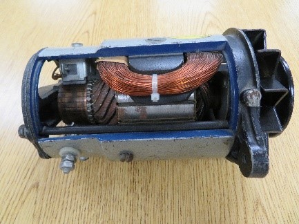
Figure 2 – Cutaway DC Motor
Electric motors, whether they are DC or AC, use these principals of magnetism and electromagnetism to produce magnetic fields that then produce rotating motion. The stator, the stationary magnetic field, is energized so that it produces a North magnetic field. If the rotor (armature), the moving magnetic field, near the stator also is producing a North magnetic field, the rotor starts moving away from the stator. Similarly, you can use the attraction of opposite poles to pull the rotor towards a stator pole. Rotation is achieved when you move the stationary and rotating magnetic fields to always have poles pushing and pulling each other. The magnetic fields are changed by changing the direction of current flow.
The rotational speed of the motor is determined by how fast you change the electromagnetic fields. The force generated is determined by the strength of the magnetic fields. And, recalling form earlier, the strength of the magnetic field is determined by the amount of current. Note: even DC motors have to have changing magnetic fields created with changing current flow direction. The result is electric motors are designed and manufactured to operate at predetermined speeds and are not easily changed. For AC electric motors, the following formula is used to determine their maximum rated speed.
\[RPM=~\frac{f~*~60}{Number~of~Pole~Pairs}~where~f~is~the~line~frequency\]
While electric motors have some limitations, they have become very important parts of lives. Most of us don’t even think about how many electric motors are in our lives. The following video will give you some idea of the many areas and places electric motors are used today.
Click on the following link to view the video.
To change the operating characteristics of DC motors, you would use rheostats (large variable resistors). This control was effective but was inefficient because there was considerable power lost in the rheostat. Controlling AC motors is very challenging because to change the speed of the motor you had to vary the input frequency or the number of pole pairs.
Semiconductor Devices
Semiconductor electronics (diodes, transistors, FETs, etc) have changed the world significantly since the transistor was invented by Bell Labs in 1947. For many years, semiconductor applications were limited by the relatively small amount of current the devices could handle. Over the years, newer devices were created and developed that could handle more and more power. In the late 1970’s, higher power devices were being developed called IGBT (Insulated Gate Bipolar Transistor).
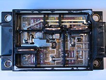
Figure 3 – IGBT Module rated at 400 A and 600V
VFD Working Principle
With these higher power semiconductor devices, controls could be developed for high power applications. One of these high power applications is electronic control of electric motors. The electronic controls for motors are called drives. For DC Motors, drives meant higher efficiencies because the DC motors were being controlled without dumping unneeded power into rheostats. In AC Motors, drives mean the speed and direction of the motors can be easily controlled.
The basic design of drives is rectifying the voltage from AC to DC. With the rectified DC voltage, you can create the output with the electrical characteristics you desire to control the motor (for example, convert 60 HZ input voltage to 30 Hz output voltage to run an AC motor at half speed). This conversion from DC to AC is done using inverter circuits. For AC motors, you need one of those basic sections for each phase of the power. That means for three-phase power there are three of these rectifications to inverter sections.

Figure 4 – Variable Frequency Drive Block Diagram
Motor Shaft Direction
The circular motion of motors produces the work of the motor. For the equipment the motor is driving, it is important to match the direction the motor turns and the direction the equipment attached to the motor needs to turn. And, frequently, it is important to reverse the direction the motor is turning and thus the equipment. During the setup of a drive, part of the procedure is to set the direction of motor shaft rotation to match the motor direction indication of the drive control.
First a quick review, what is meant by CW – Clockwise and CCW – Counterclockwise? With digital clocks everywhere today, it is easy to forget analog clocks and the movement of hands. As is shown in Figure 5, CW or clockwise is when the movement is in the direction the hands of a clock move. And, likewise, CCW or counterclockwise is when the movement is in the opposite direction.
Figure 5 – Clock Face
The next item is to look at the ends of a motor. Which end of the motor do you look at to determine the direction of shaft rotation? Figures 6a, 6b, and 6c show three different views of an electric motor for reference.
Three Phase Motor Connection
We are very familiar with the 120 VAC power in our everyday lives. This is called single phase (1Φ) power. For single phase power. There is a hot or the source power. For wiring such as in your home, it is the black wire. There is also what is referred to as the return or neutral. Again, in your home, this would be the white wire. There is a third wire known as GROUND. The ground wire is either bare copper color or green. Unless you having training for electricity, do NOT try checking your house wiring.
Figure 7 – Single Phase Voltage Graph
Figure 8 – Single Phase Wire
Figure 7 shows a graph of a single phase voltage or current wave. It is a sine wave. Figure 8 show typical 120 VAC wiring. This is found usually where 120 VAC is found.
Three phase (3Φ) power is a more efficient way to transmit power. There are three wires called Phase 1 (Leg 1), Phase 2 (Leg 2), and Phase 3 (Leg 3). For AC (Alternating Current), 360° is one cycle. This is same as 360° for a circle. If Leg 1 starts at t = 0 seconds (time) or 0 degrees and voltage or current is 0 V or 0 A, the voltage over one cycle or 360° is one full sine wave.
In three-phase power, Leg 2 at t = 0 seconds starts at 120° when compared to Leg 1. And, the third leg, Leg 3 starts at 240° when compared to Leg 1 or 120° from Leg 2.
Figure 9 – Three Phase Voltage Graph
On three-phase electrical motors, there are three power leads. There may also be a fourth ground lead that would be connected to earth ground. The three-phase leads on a three-phase motor are labeled T1, T2, and T3. The basic setup of three-phase motors is L1 – T1, L2 – T2, and L3 – T3. Table 1 shows the connections in table form.
| Line | Motor |
| L1 | T1 |
| L2 | T2 |
| L3 | T3 |
Table 1 – Three Phase Motor Wiring
To reverse the direction of the shaft rotation, it is as simple as switching two of the three legs. For example, switching L1 and L3 will change the direction of rotation. Table 2 shows the various combinations of wiring to reverse motor direction.
| Line | Motor | Line | Motor | Line | Motor | ||
| L3 | T1 | L1 | T1 | L1 | T1 | ||
| L2 | T2 | L3 | T2 | L2 | T2 | ||
| L1 | T3 | L2 | T3 | L3 | T3 |
Table 2 – Three Phase Motor Wiring – Reverse Direction
In industrial applications, the motor wiring is determined when setting up the equipment. The motor is wired and following all applicable safety rules and guidelines, the motor is energized and the shaft rotation direction is determined. The shaft rotation is compared to the required shaft rotation direction. If the shaft rotation direction is wrong, two of the leads are reversed and the shaft rotation direction is checked. Usually, this is the first and last time the shaft rotation needs to be checked.
For the Motor Control Panels described in the Panel Overview section, the motor is connected using terminal blocks in the lower right portion of the panel. On the section labeled STR, there are three terminals labeled, T1 T2 T3. The three-phase motor leads are connected here. See Figure 10 – Three Phase Motor Wiring – Control Panel. (For more information about the Control Panel see the section Control Panel Overview).
Figure 10- Three Phase Motor Wiring – Control Panel
In this tutorial, we use the ABB ACS 355 drive. For the ABB ACS 355 Drive, the three-phase inputs are still L1 L2 and L3. The connections at the drive to the motor are labeled U2 V2 and W2. In Figure 10 – Three Phase Motor Wiring – Control Panel, with the section labeled VFD, you will see the terminals labeled U2 V2 and W2.
Figure 11 – Three Phase Motor – Wire Number
The motor used as a reference in this tutorial is the Marathon Electric Model LVJ, the three-phase wiring uses black wires. To determine where each phase is connected, the individual wires in the motor cable are labeled 1, 2, and 3. If you look very closely at Figure 11 – Three Phase motor – Wire Number, you can see in the circled area the number 2. The other two wires are labeled 1 and 3 respectively. Table 3 shows the wiring between the ABB ACS 350 Drive and the Marathon Motor.
| ABB Drive | Motor |
| U2 | 1 |
| V2 | 2 |
| W2 | 3 |
Table 3- ABB Drive – Marathon Motor Wiring
Again, to reverse the direction of motor or shaft rotation, you switch the leads as described earlier. Table 4 shows how to switch the Motor Leads using the ABB Drive.
| ABB Drive | Motor |
| U2 | 3 |
| V2 | 2 |
| W2 | 1 |
Table 4 – ABB Drive Marathon Motor – Reverse Direction Wiring
For Complete Operation of Variable Frequency Drive, Watch the following Video:
https://www.youtube.com/watch?v=7sbbebFuByI