The article provides an overview of Mesh Current Analysis, a method used to simplify the process of solving planar electrical networks by applying Kirchhoff’s voltage law to individual meshes. It outlines the key rules for mesh setup, the process for forming equations, and includes a detailed example to demonstrate the solution of mesh currents and voltage drops across resistors.
Mesh Current Analysis is a technique that simplifies and speeds up writing the simultaneous equations for solving various resistance networks. The format for mesh equations is straightforward, but it cannot handle some of the networks that we can solve with the loop procedure.
A mesh is a closed loop that does not enclose any circuit elements. Therefore, the circuit diagram cannot contain any conductors that cross without being joined at the point of crossing. In other words, the network diagram must be strictly two-dimensional or planar.
The mesh format requires all sources to be voltage sources. We must convert any current sources to equivalent voltage sources before we use the mesh format. Instead of choosing convenient tracing loops, we draw a current loop for each mesh.
All mesh currents must have the same direction, either clockwise or counterclockwise. The more common choice is clockwise. These rules provide a standard format for every mesh equation.
In the loop procedure, we write equations for voltage drops around the current loops and then rewrite the Kirchhoff’s voltage-law equations to collect the current terms. In the mesh format, we go directly to this second step.
We can use the network shown in Figure 1 to illustrate the mesh format. The network is clearly planar and the four meshes have no internal electric components.
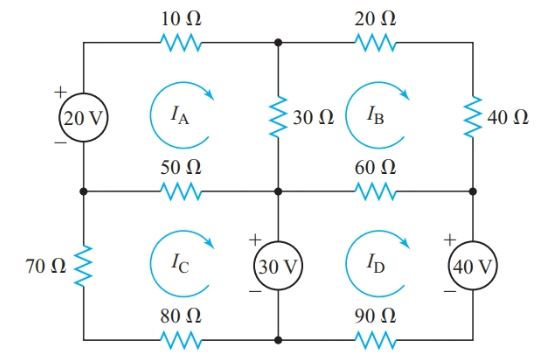
Figure 1 Mesh network for Example 1
For any particular mesh current, all other currents through common circuit elements are in the opposite direction. For example, IA and IB flow through the 30-V resistor in opposite directions. The mesh equation for mesh A has the form
${{R}_{T}}{{I}_{A}}-{{R}_{AB}}{{I}_{B}}-{{R}_{AC}}{{I}_{C}}=\sum{E}$
Where RT is the total resistance around mesh A, RAB is the resistance that is common to mesh A and mesh B, RAC is the resistance that is common to mesh A and mesh C, and ΣE is the algebraic sum of the voltage sources around the mesh.
Where IA passes inside a voltage source from its negative terminal to its positive terminal, E is positive. If the direction of IA through a voltage source is from the positive terminal to the negative terminal, E is negative.
Mesh Current Analysis Example 1
Find the magnitudes and polarities of the voltage drops across the 30-Ω, 50- Ω, and 60- Ω resistors in the network shown in Figure 1.
Solution
Using the mesh format, write a Kirchhoff’s voltage-law equation for each of the four meshes in Figure 1. In this example, the resistances are in ohms and the potential differences are in volts, so the currents will be in amperes.
$\begin{align} & \left( 10+30+50 \right){{I}_{A}}-30{{I}_{B}}-50{{I}_{C}}=20 \\ & \left( 30+20+40+60 \right){{I}_{B}}-30{{I}_{A}}-60{{I}_{D}}=0 \\ & \left( 80+70+50 \right){{I}_{C}}-50{{I}_{A}}=-30 \\ & \left( 90+60 \right){{I}_{D}}-60{{I}_{B}}=30-40 \\\end{align}$
Collecting like terms in each equation gives
\[\begin{align} & 90{{I}_{A}}-30{{I}_{B}}-50{{I}_{C}}=20\cdots \left( 1 \right) \\ & -30{{I}_{A}}+150{{I}_{B}}-60{{I}_{D}}=0\cdots \left( 2 \right) \\ & -50{{I}_{A}}+200{{I}_{C}}=-30\cdots \left( 3 \right) \\ & -60{{I}_{B}}+150{{I}_{D}}=-10\cdots \left( 4 \right) \\\end{align}\]
Unfortunately, the calculations for solving fourth-order determinants are not as simple as those for second- and third-order determinants. We can get around this problem by eliminating one of the unknowns. From Equation 4,
\[{{I}_{D}}=\frac{60{{I}_{B}}-10}{150}\]
Substituting for ID in Equation 2 gives
$-30{{I}_{A}}+150{{I}_{B}}-\left( 24{{I}_{B}}-4 \right)=0$
We now have three simultaneous equations:
\[\begin{align} & \begin{matrix} 90{{I}_{A}}-30{{I}_{B}}-50{{I}_{C}}=20 & {} & \left( 1 \right) \\\end{matrix} \\ & \begin{matrix} -30{{I}_{A}}-126{{I}_{B}}=-4 & {} & \left( 5 \right) \\\end{matrix} \\ & \begin{matrix} -50{{I}_{A}}+200{{I}_{C}}=-30 & {} & \left( 3 \right) \\\end{matrix} \\\end{align}\]
\[{{I}_{A}}=\frac{\left| \begin{matrix} 20 & -30 & -50 \\ -4 & 126 & 0 \\ -30 & 0 & 200 \\\end{matrix} \right|}{\left| \begin{matrix} 90 & -30 & -50 \\ -30 & 126 & 0 \\ -50 & 0 & 200 \\\end{matrix} \right|}=\frac{291,000}{1,773,000}=0.164A\]
\[{{I}_{B}}=\frac{\left| \begin{matrix} 90 & 20 & -50 \\ -30 & -4 & 0 \\ -50 & -30 & 200 \\\end{matrix} \right|}{D}=\frac{13,000}{1,773,000}=0.0073A\]
\[{{I}_{C}}=\frac{\left| \begin{matrix} 90 & -30 & 20 \\ -30 & 126 & -4 \\ -50 & 0 & -30 \\\end{matrix} \right|}{D}=\frac{-193,200}{1,773,000}=-0.109A\]
\[{{I}_{C}}=\frac{60\times 7.33\times {{10}^{-3}}-10}{150}=-0.064A\]
$\begin{align} & {{I}_{30}}={{I}_{A}}-{{I}_{B}}=0.164-0.0073=157mA \\ & {{V}_{30}}=30\Omega \times 157mA=4.7V\left[ positive\text{ }at\text{ }top \right] \\ & {{I}_{50}}={{I}_{A}}-{{I}_{C}}=0.164+0.109=273mA \\ & {{V}_{50}}=50\Omega \times 273mA=14V\left[ positive\text{ }on\text{ }the\text{ }right \right] \\ & {{I}_{60}}={{I}_{B}}-{{I}_{D}}=0.0073-0.064=71mA \\ & {{V}_{60}}=60\Omega \times 71mA=4.3V\left[ positive\text{ }on\text{ }the\text{ }right \right] \\\end{align}$
It is important to understand that Mesh analysis can be applied to either AC resistive circuit or DC resistive circuit. In any type of network, the numbers of linear equations are dependent on the number of loop currents.
- You May Also Read: Mesh Analysis using Matlab
Mesh Current Analysis Key Takeaways
Mesh Current Analysis is a powerful tool for simplifying and solving complex planar electrical circuits efficiently. By applying a systematic approach based on Kirchhoff’s Voltage Law and standard mesh setup rules, engineers and students can reduce complicated networks into a manageable set of linear equations. The ability to calculate current distribution and voltage drops across individual components is essential in designing and analyzing circuits in various real-world applications. These include power distribution systems, electronic devices, and integrated circuits, where accurate current and voltage calculations are critical for functionality, safety, and efficiency.