The article provides an overview of wind turbine types—horizontal-axis and vertical-axis—and their respective characteristics, as well as a general description of the key mechanical, electrical, and control components of horizontal-axis wind turbines. It also introduces mechanical modeling of wind turbine drivetrains using both detailed six-mass and simplified two-mass models.
Wind turbines are categorized based on the orientation of their spin axis into horizontal-axis wind turbines (HAWT) and vertical-axis wind turbines (VAWT).
VAWT have their rotor shaft transverse to the wind (but not necessarily vertical), and the main components are located at the base of the turbine; that is, the generator and gearbox are located close to the ground, facilitating service and repair.
VAWT capture wind from any direction without being pointed towards the main wind direction. Typical designs such as Savonius, Darrieus, and Giromill have significant torque variation during each revolution causing bending moments on the blades with consequent mechanical stress and material fatigue.
VAWT have been studied and deployed in the past few years, but the recent commercial success of wind turbines is really due to HAWT.
Figure 1 shows the typical wind turbine components in a HAWT. There are three categories of components: mechanical, electrical, and control. The following is a brief description of the main components:
- The tower is the physical structure that holds the wind turbine. It supports the rotor, nacelle, blades, and other wind turbine equipment. Typical commercial wind towers are usually 50–120 m long and they are constructed from concrete or reinforced steel.
- Blades are physical structures, which are aerodynamically optimized to help capture the maximum power from the wind in normal operation with a wind speed in the range of about 3–15 m/s. Each blade is usually 20 m or more in length, depending on the power level.
- The nacelle is the enclosure of the wind turbine generator, gearbox, and internal equipment. It protects the turbine’s internal components from the surrounding environment.
- The rotor is the rotating part of the wind turbine. It transfers the energy in the wind to the shaft. The rotor hub holds the wind turbine blades while connected to the gearbox via the low-speed shaft.
- Pitch is the mechanism of adjusting the angle of attack of the rotor blades. Blades are turned in their longitudinal axis to change the angle of attack according to the wind directions.
- The shaft is divided into two types: low and high speed. The low-speed shaft transfers mechanical energy from the rotor to the gearbox, while the high-speed shaft transfers mechanical energy from gearbox to generator.
- Yaw is the horizontal moving part of the turbine. It turns clockwise or anticlockwise to face the wind. The yaw has two main parts: the yaw motor and the yaw drive. The yaw drive keeps the rotor facing the wind when the wind direction varies. The yaw motor is used to move the yaw.
- The brake is a mechanical part connected to the high-speed shaft in order to reduce the rotational speed or stop the wind turbine over speeding or during emergency conditions.
- Gearbox is a mechanical component that is used to increase or decrease the rotational speed. In wind turbines, the gearbox is used to control the rotational speed of the generator.
- The generator is the component that converts the mechanical energy from the rotor to electrical energy. The most common electrical generators used in wind turbines are induction generators (IGs), doubly fed induction generators (DFIGs), and permanent magnet synchronous generators (PMSGs).
- The controller is the brain of the wind turbine. It monitors constantly the condition of the wind turbine and controls the pitch and yaw systems to extract optimum power from the wind.
- Anemometer is a type of sensor that is used to measure the wind speed. The wind speed information may be necessary for maximum power tracking and protection in emergency cases.
- The wind vane is a type of sensor that is used to measure the wind direction. The wind direction information is important for the yaw control system to operate.
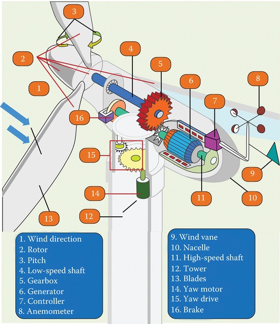
Figure 1 Wind turbine components.
The drivetrain of a wind turbine is depicted in Figure 2a. It shows a six-mass drivetrain model with six inertias: three blade inertias (JB1, JB2, and JB3), hub inertia (JH), gearbox inertia (JGB), and generator inertia (JG).
The angular positions for blades, hub, gearbox, and generator are represented by θB1, θB2, θB3, θH, θGB, and θG, while their corresponding angular speeds are ωB1, ωB2, ωB3, ωH, ωGB, and ωG.
The elasticity between adjacent masses is expressed by their spring constants KHB1, KHB2, KHB3, KHGB, and KGBG and the mutual damping between adjacent masses is expressed by dHB1, dHB2, dHB3, dHGB, and dGBG.
There are torque losses because of external damping elements of individual masses, represented by DB1, DB2, DB3, DH, DGB, and DG.
This model requires a generator torque (TE) and three individual aerodynamic torques acting on each blade (TB1, TB2, TB3).
The sum of the blade torques develops the turbine torque, TWT. The aerodynamic torques acting on the hub and gearbox are assumed to be zero.
Because the six-mass model is very complex, usually an equivalent two-mass model is used with equivalent shaft stiffness K2M, that is, the masses of turbine and gearbox are lumped together into one mass, such simplified model is represented in Figure 2b.
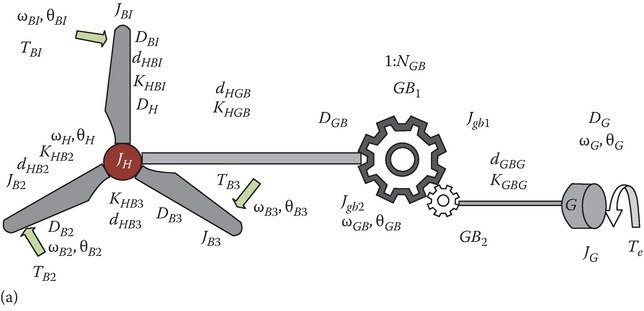
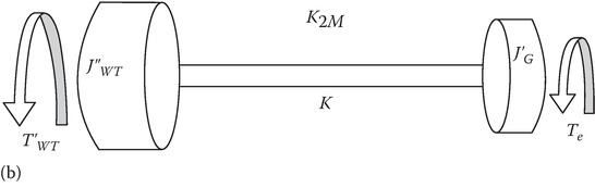
Figure 2 Mechanical model of a drivetrain of a wind turbine: (a) six-mass drivetrain, (b) two-mass equivalent model.
Wind Turbine Components Key Takeaways
Understanding the different types of wind turbines—particularly the more commercially successful horizontal-axis wind turbines (HAWT)—and their key components is essential for the development, operation, and maintenance of efficient wind energy systems. The detailed mechanical modeling of wind turbine drivetrains, especially through six-mass and two-mass models, plays a critical role in analyzing performance, predicting mechanical stresses, and designing robust control strategies. These insights are vital for optimizing energy capture, minimizing mechanical failures, and improving the reliability and lifespan of wind turbines—making them crucial in the broader context of sustainable energy applications and the growing global demand for renewable power sources.