With the exception of a special class of materials called superconductors, all materials have resistance, which is the opposition to current. Conductors are generally metallic materials with low resistance, whereas insulators are materials with high resistance. When there is current through a resistive material, heat is produced by the collisions of electrons and atoms. Even wire, which has a very small resistance, can become warm when there is sufficient current through it.
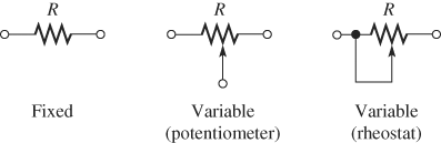
Figure 1: Schematic Symbols for Fixed and Variable Resistors
Resistance is the opposition to current and is symbolized by R. Its unit is the ohm, symbolized by the Greek letter Ω
One ohm (1 Ω) of resistance exists when there is one ampere (1 A) of current in a material with one volt (1 V) applied across the material.
Resistors
Resistors are components that are designed to have a certain amount of resistance between their leads or terminals. The principal applications of resistors are to limit current; divide voltage; and, in certain cases, generate heat. Although there are many types of resistors and they come in many shapes and sizes, they can all be placed in one of two main categories: fixed or variable. The symbols for a fixed resistor and two variable resistors are shown in Figure 1. Variable resistors are subdivided into potentiometers (pots)—with three terminals—and rheostats—with two terminals. Notice in Figure 1, however, that a potentiometer can be connected as a rheostat by connecting the center terminal to one side. Potentiometers are used to control voltage; rheostats are used to control current.
Fixed Resistors
Fixed resistors have resistance values that cannot be altered. They are available with a large selection of values and power ratings that are set by the manufacturer. Fixed resistors are constructed using various methods and materials. A common type of fixed resistor is the carbon-composition type, which is made with a mixture of finely ground carbon, insulating filler, and a resin binder. Figure 2 shows the construction of a typical carbon-composition resistor.
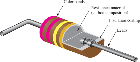
Figure 2: Cutaway View of a Carbon-Composition Resistor
Another type of fixed resistor for low-resistance precision applications is the wire-wound resistor. Wire-wound resistors are available either as small precision resistors or as large power resistors. They have excellent low-frequency characteristics, but they are not suitable for use at high frequencies. They are constructed by wrapping a resistive wire around an insulating rod and then sealed.
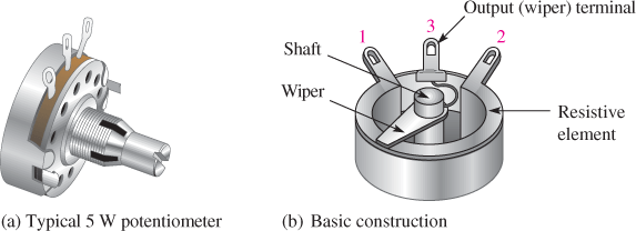
Figure 3: Examples of Potentiometers with Construction Views
Variable Resistors
Variable resistors have resistance values that can be varied. They are also available in different types, including carbon-composition, film, and wire-wound. Potentiometers are constructed with a rotating shaft connected to a wiper, similar to the one shown in Figure 3(a). The center terminal is connected to the wiper arm, which is controlled by rotating the shaft. For applications requiring more precise control, potentiometers are available with multiple turns and in a multi-turn linear arrangement, as shown in Figure 3(c).
Wire Resistance
Although copper is an excellent conductor and is widely used in electronic circuits, it has some resistance. For many applications, the resistance of wire can be ignored; but in some cases, it can affect a circuit and needs to be considered. You may have seen low-voltage yard lights that grow dimmer the farther they are from the source. In this case, the wire resistance has affected the circuit. The problem is reduced if a larger-diameter wire (greater cross-sectional area) is used or if the lights are moved closer to the source (because a shorter wire has less resistance). A wire can overheat due to the resistance when there is too much current. Wire gauges are used throughout the world to specify the size of the wire.
American Wire Gauge
The size and type of wire that is appropriate for a given application depends on a number of factors, including the length, the maximum amount of current, and the environment that the wire is in, among other factors. The diameter of the wire is arranged according to standard gauge numbers called American Wire Gauge (AWG) sizes.
The larger the gauge number, the smaller the wire and the greater the resistance per unit length. For example, 12 gauge is common in household wiring, and 24 gauge is useful for telephone circuits. Wire as small as a human hair is number 40 gauge; even smaller sizes are used in certain applications. The AWG is related to the cross-sectional area of the wire; the common English unit for the cross-sectional area of wires is the circular mil (CM). One circular mil is the area of a wire that is one-thousandth of an inch (one mil) in diameter. A circular mil is illustrated in Figure 4.
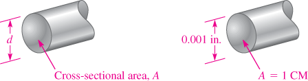
Figure 4: Circular Mil
For reference, the diameter, resistance per 1,000 feet, resistance per km, and current capacity (ampacity) of some common AWG copper wire sizes are given in Table 1. Ampacity is the maximum current a wire can carry under certain specified conditions. When the diameter of the wire becomes larger, the AWG number is smaller and the wire is rated for more current. After the AWG size gets to 1, the next size wire is 1/0, which is called a one ought, which in turn means one zero (0). The next three sizes are two ought (2/0), three ought (3/0), and four ought (4/0).
Because wire has resistance, the current through it causes power in the form of heat to be dissipated. Thus, if there is too much current, the wire overheats.
Ampacity ratings vary with temperature and the type of cable. Other ampacity ratings are also provided based on the National Electric Code (NEC).
For example, AWG 12 is rated at 25 A in free air and 20 A as part of a three-conductor cable for a temperature of 30°C Also, the NEC provides specifications that include the maximum number of amperes and fuse or breaker requirements for various wires (normally referred to as conductors in the code).
In addition, there are specific requirements for conditions such as buried conductors, conductors exposed to sunlight, or conductors installed in damp locations such as those used in solar panel installations. The current capacity is derated for these conditions and more when there are a number of wires in a conduit or bundle. This is very important in renewable energy systems as bundled wires in hot locations are common. Always check the NEC for ratings in specific applications and the code requirement in your area before installing any wiring,
Table 1 Normal NEC Current Rating and Wire Resistance of Selected Sizes of Copper Wire
| American Wire Gauge (AWG) Wire Size | Current Capacity (A) of Copper Wire | Resistance (Ω) per 1,000 Feet | Resistance (Ω) per Kilometer |
| 16 | 15 | 4.016 | 13.176 |
| 14 | 20 | 2.525 | 8.284 |
| 12 | 25 | 1.588 | 5.210 |
| 10 | 30 | 0.9989 | 3.277 |
| 8 | 40 | 0.6282 | 2.061 |
| 6 | 55 | 0.3951 | 1.296 |
| 4 | 70 | 0.2485 | 0.815 |
| 3 | 85 | 0.187 | 0.614 |
| 2 | 95 | 0.1563 | 0.513 |
| 1 | 110 | 0.1239 | 0.406 |
| 1/0 | 125 | 0.0983 | 0.323 |
| 2/0 | 145 | 0.0779 | 0.256 |
| 3/0 | 165 | 0.0618 | 0.203 |
| 4/0 | 195 | 0.049 | 0.161 |
EXAMPLE 1
Find the resistance of 2,500 feet of AWG 12 copper wire.
Solution
From Table 1, the resistance of AWG 12 copper wire is 1.588 Ω ft. This means that 2,500 ft. will have a resistance that is
\[R=(2,500ft)(1.588\Omega /1,000ft)=3.97\Omega \]
Ohm’s Law
Georg Simon Ohm formulated Ohm’s law, which is named in his honor. Ohm’s law expresses the relationship among voltage (V), current (I), and resistance (R). Ohm’s law can be expressed in three equivalent forms: one for voltage, one for current, and one for resistance. It allows you to determine any one of the quantities (V, I, or R) if you know the other two.
Formula for Voltage
You can use Ohm’s law to find the voltage when you know the current and resistance. Voltage equals current times resistance.
\[V=IR\]
Formula for Current
You can use Ohm’s law to find the current when you know the voltage and resistance. Current equals voltage divided by resistance.
\[I=V/R\]
Formula for Resistance
You can use Ohm’s law to find the resistance when you know the current and voltage. Resistance equals voltage divided by current.
\[R=V/I\]
The three formulas (V = IR, I = V/R, and R = V/I) are, of course, equivalent. Figure 5 can help you remember the relationship among voltage, current, and resistance.
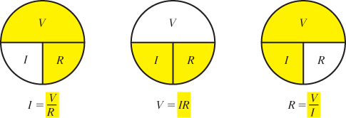
Figure 5: Memory Aid for Ohm’s Law
EXAMPLE 2
- Determine the voltage when the current is 2 A and the resistance is 10 Ω.
Solution
\[V=IR=(2A)(10\Omega )=20V\]
- Determine the current when the voltage is 48 V and the resistance 20 Ω
Solution
\[I=V/R=48V/20\Omega =2.4A\]
- Determine the resistance when the voltage is 120 V and the current is 8 A.
Solution
\[R=V/I=120V/8A=15\Omega \]
Review
- Define resistance and name its unit.
- What are the two categories of resistor?
- Name two types of a variable resistor and draw the schematic symbol for each.
- What is a circular mil?
- What does the AWG number of a wire indicate?
- What is meant by the term ampacity?
- Write the Ohm’s law formula for voltage in terms of current and resistance.
- Write the Ohm’s law formula for current in terms of voltage and resistance.
- Write the Ohm’s law formula for resistance in terms of voltage and current.
- If the voltage in a circuit is fixed and the resistance is increased, what happens to the current?
Answers
- Resistance is opposition to current; the unit is the ohm.
- Fixed resistors and variable resistors
- Potentiometers and rheostats; the schematic symbols are shown in Figure 3.
- A circular mil is the area of a wire that is one-thousandth of an inch (one mil) in diameter.
- AWG stands for “American Wire Gauge” and the system uses a number related to the cross-sectional area of the wire.
- Ampacity is the maximum current a wire can carry under certain specified conditions.
- V = IR
- I=V/R
- R=V/I
- The current will decrease.
