AC motor drives are referred to as variable frequency drives, adjustable frequency drives, inverter drives, vector drives, direct torque control drives, and closed-loop drives.
Regardless of how an AC drive is referred to, its primary function is to convert the incoming supply power to an altered voltage level and frequency that can safely control the motor connected to the drive.
AC motor drives are designed to operate 3φ AC motors regardless of whether the drive is designed for 1φ power (115 VAC or 230 VAC), 3φ power, or DC power. The speed of an AC motor is determined by the number of stator poles and the frequency of the AC power supply.
AC motor drives control the speed of a motor by varying the frequency of the power applied to the motor. See Figure 1. The lower the frequency applied to a motor, the slower the motor speed. For example, an AC motor rated for 1730 rpm at 60 Hz operates at 1730 rpm at 60 Hz, 865 rpm at 30 Hz, and 432.5 rpm at 15 Hz.
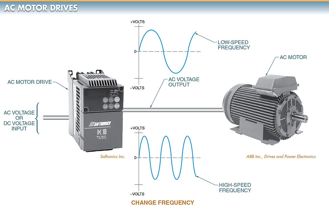
Figure 1. An AC motor drive controls the speed of a motor by varying the frequency of the power applied to the motor.
AC Motor Variable Frequency Drive Components
The three main components of an AC motor drive are the converter, DC bus, and inverter.
The converter (rectifier) receives incoming AC voltage and changes it to DC voltage. If the AC input voltage is different from AC output voltage sent to a motor, the converter must first step up or step down the AC voltage to the proper voltage source level. For example, an electric motor drive supplied with 115 VAC that delivers 230 VAC to a motor requires a step-up transformer to increase the input voltage. A drive supplied with 230 VAC would be stepped down to deliver 115 VAC. See Figure 2.
The DC bus filters the voltage and maintains the proper DC voltage level. The DC bus may also deliver DC to the inverter for conversion back to AC. The inverter controls the speed of a motor by controlling frequency and controls motor torque by controlling the voltage sent to the motor.
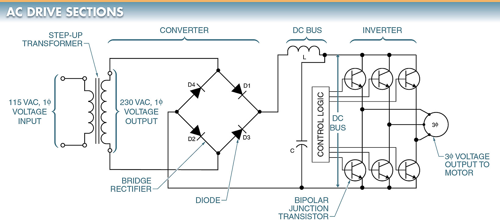
Figure 2. The three main sections of an AC motor drive are the converter, DC bus, and inverter.
Converters
A converter is an electronic device that changes AC voltage into DC voltage. Converters in electric motor drives are 1φ full-wave rectifiers, 1φ bridge rectifiers, or 3φ full-wave rectifiers. Small AC motor drives supplied with 1φ power use 1φ full-wave or bridge rectifiers. Most electric motor drives are supplied with 3φ power, which requires 3φ full-wave rectifiers. See Figure 3.
AC Motor Drive Power Converter Requirements
In order for a converter to deliver the proper DC voltage to the DC bus of an AC motor drive, the converter must be connected to the proper power supply. AC motor drives operate satisfactorily only when connected to the proper power supply.
The power supply must be at the correct voltage level and frequency and must also provide enough current to operate an AC motor drive at full power. When a power supply cannot deliver enough current, the available voltage to an AC motor drive drops when the drive is required to deliver full power.
Current to an AC motor drive is limited by the size of the conductors to the drive, fuse and circuit breaker sizes, and the transformer(s) delivering power to the system.
The supply voltage to an AC motor drive must be checked when additional loads or drives are installed, serviced, or added to a system. To determine whether an AC motor drive is underpowered, the voltage at the drive is measured under no-load and full-load operating conditions. See Figure 4.
A voltage drop greater than 3% between no-load and full-load conditions indicates that the AC motor drive is underpowered and/or overloaded.
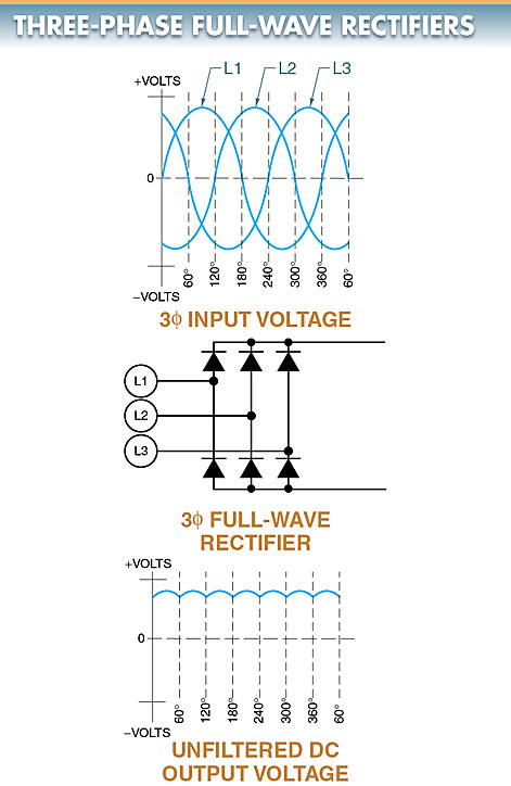
Figure 3. Most AC motor drives use 3φ full-wave rectifiers to convert AC voltage to DC voltage to supply the DC bus.
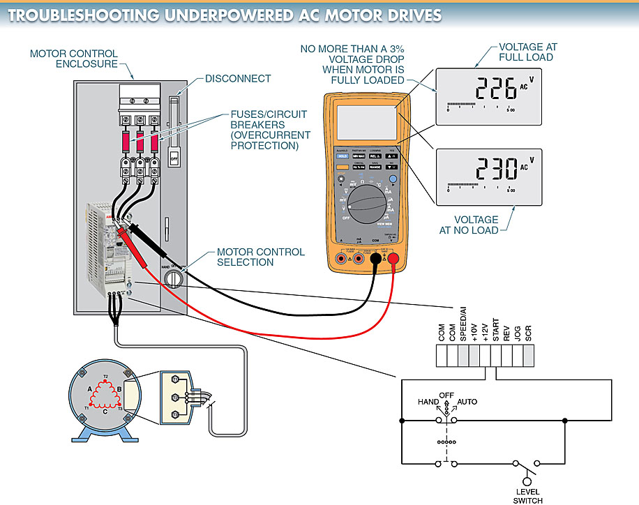
Figure 4. AC motor drive voltage should be measured under no-load and full-load operating conditions to determine whether a drive is underpowered.
Voltage drop is found by applying the following formula:
$\begin{align} & {{V}_{D}}={{V}_{NL}}-{{V}_{FL}} \\ & Where \\ & {{V}_{D}}=Voltage\text{ }Drop\text{ }(in\text{ }V) \\ & {{V}_{NL}}=No-Load\text{ }Voltage\text{ }(in\text{ }V) \\ & {{V}_{FL}}=Full-Load\text{ }Voltage\text{ }(in\text{ }V) \\\end{align}$
Example: Calculating Voltage Drop
What is the voltage drop when an AC motor drive is measured to have 230 V with no load and 226 V under full load?
Solution
${{V}_{D}}={{V}_{NL}}-{{V}_{FL}}=230-226=4V$
When the supply voltage to an AC motor drive is measured, it is recommended to check the measured voltage against the rated input voltage of the drive. Large-horsepower AC motor drives are connected to the high voltage to reduce the amount of current required.
AC voltage sources vary due to fluctuations within the power distribution system. AC loads, including motor drives and motors, are designed to operate within a specified voltage range. Operating outside the specified voltage range can cause a motor drive to operate improperly and/or incur damage over time.
Electrical loads operating at low voltages are less likely to be damaged than loads operating at high voltages. Operating at a voltage less than the rated voltage causes lamps to dim, heating elements to produce less heat, computers to lose memory and/or reboot, and motors to produce less torque. Although operating at less than rated voltage is not desirable for electrical loads, it normally does not cause damage.
Operating at higher than rated voltage causes lamps to fail, heating elements to burn out (open), computer circuits to become permanently damaged, and motor insulation to be destroyed.
AC loads are rated for proper operation at a voltage that is ±10% of the device’s rated voltage. Because higher voltages are more damaging, some devices with higher voltage ratings have a +5% to –10% voltage rating to protect them from the high voltage side.
Tech Fact
Most drives display a “low voltage” fault when the drive turns off the motor due to a low voltage condition. When troubleshooting a low-voltage fault, measurements are taken of the voltage into the drive, the voltage out of the drive (using the MIN/MAX mode during a complete cycle of the motor to determine whether there is a power feed or drive output problem), and the drive’s DC bus voltage to eliminate a drive problem.
DC Buses
DC buses filter and maintain the proper voltage level. DC buses (links) include DC filter components and are supplied with DC voltage by the converter.
The capacitors and inductors in the DC bus filter and maintain the proper voltage level. DC bus voltage is typically about 1.4 times the AC supply voltage to an AC motor drive.
Circuit Protection
A bridge rectifier receives incoming AC supply power and converts the AC voltage to fixed DC voltage. The fixed DC voltage powers the DC bus of the AC motor drive.
To prevent damage to the diodes in the converter and to the AC motor drive electronic circuits, protection against transient voltages must be included in the drive.
A transient voltage is a high-energy, high-voltage, short-duration spike in an electrical system.
All electrical systems experience some type of transient voltage. Lightning strikes and utility switching cause high-energy-level transient voltages. High-energy- level transients seldom occur but are quite damaging to equipment if allowed to travel through a power distribution system and into electrical equipment.
Low-energy-level transients are transient voltages commonly caused when motors and equipment are switched on and off. Low-energy-level transients occur often but do not cause immediate equipment damage. Low-energy-level transients cause malfunctions such as processing errors and damage to equipment over time.
The electronic circuits of an AC motor drive require protection against transient voltages. Protection methods include proper motor drive wiring, grounding, shielding for power lines, and surge suppressors.
A surge suppressor is an electrical device that provides protection from transient voltages by limiting the level of voltage allowed downstream from the surge suppressor.
Surge suppressors are installed at service entrance panels, distribution panels feeding motor drives, and/or the incoming power lines to a drive. Normally, a surge suppressor consists of metal-oxide Varistors (MOVs) connected to the converter of a motor drive. See Figure 5.
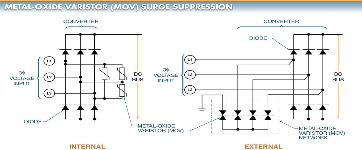
Figure 5. Metal-oxide Varistors (MOVs) are added to the converter of an AC motor drive to reduce the amount of transient voltage entering the motor drive.
MOVs are designed for surge suppression of damaging transient voltages. When high-voltage transients enter an AC motor drive, MOVs change electrical state from high resistance (open switch) to low resistance (closed switch). In a low-resistance state, MOVs absorb and/or divert transient voltage spikes.
MOVs limit the level of transient voltages so voltages do not exceed the maximum voltage rating of the rectifier diodes.
Capacitors
A capacitor is an electrical device designed to store a voltage charge by means of an electrostatic field. Capacitance (C) is the ability to store energy in the form of an electrical charge.
Capacitors in a DC bus are charged from rectified DC voltage produced by the converter. Capacitors oppose a change in voltage and, when DC bus voltage starts to drop, they discharge a voltage back into the system to stop the drop-in voltage.
The main function of capacitors in a DC bus is to maintain proper voltage levels when voltage fluctuates. See Figure 6.
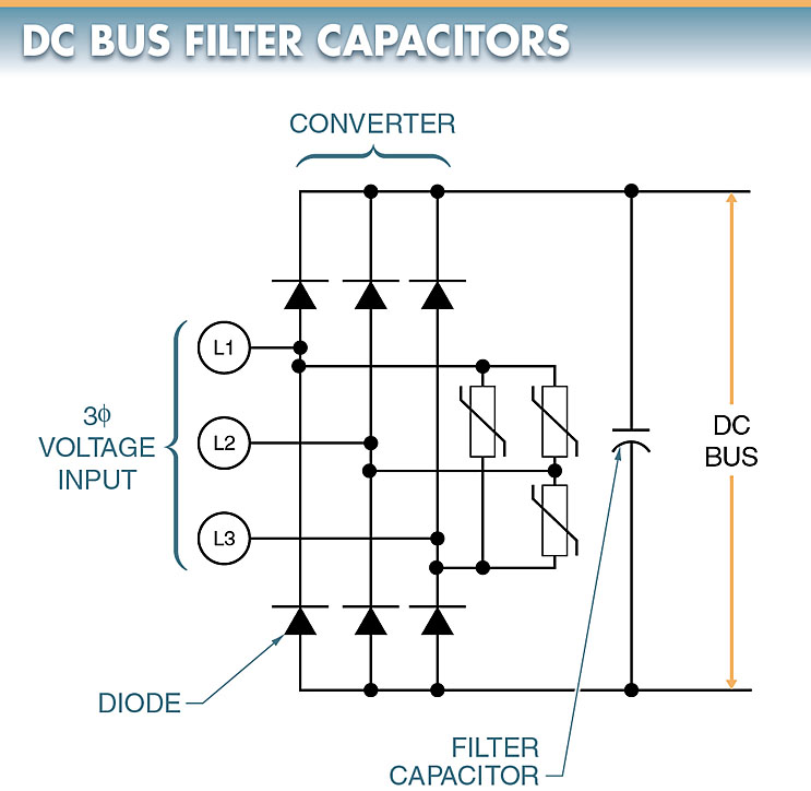
Figure 6. Capacitors are added to filter or smooth the DC bus voltage.
Inverters
An inverter is an electronic device that changes DC voltage into AC voltage.
Inverters in an AC motor drive are the most important part of the drive because the inverter determines the voltage level, voltage frequency, and amount of current that a motor receives.
AC motor drive manufacturers are continuously developing inverters that can control motor speed and torque with the fewest problems. The main problem for manufacturers is to find a high-current, fast-acting solid-state switch that has the least amount of power loss (voltage drop).
Voltage and Frequency
The voltage applied to the stator of an AC motor must be decreased by the same amount as the frequency. The motor heats excessively and damage occurs to the windings if the voltage is not reduced when the frequency is reduced.
The motor does not produce its rated torque if the voltage is reduced more than required. The ratio between the voltage applied to the stator and the frequency of the voltage applied to the stator must be constant. This ratio is referred to as the volts-per-hertz (V/Hz) ratio (constant volts-per-hertz characteristic).
The volts-per- hertz (V/Hz) ratio is the relationship between voltage and frequency that exists in a motor. The motor develops rated torque if this relationship is kept constant (linear).
The volts-per-hertz ratio for an induction motor is found by dividing the rated nameplate voltage by the rated nameplate frequency. To find the volts-per-hertz ratio for an AC induction motor, the following formula is applied:
$\begin{align} & \frac{V}{Hz} \\ & Where \\ & \text{ }V/Hz\text{ }=\text{ }volts-per-hertz\text{ }ratio\text{ } \\ & V\text{ }=\text{ }rated\text{ }nameplate\text{ }voltage\text{ }(in\text{ }V)\text{ } \\ & Hz\text{ }=\text{ }rated\text{ }nameplate\text{ }frequency\text{ }(in\text{ }Hz) \\ & \\\end{align}$
Above approximately 15 Hz, the amount of voltage required to keep the volts-per-hertz ratio linear is a constant value. Below 15 Hz, the voltage applied to the motor stator may be boosted to compensate for the large power loss AC motors have at low speed. The amount of voltage boost depends on the motor. See Figure 7.
A motor drive can be programmed to apply a voltage boost at low motor speeds to compensate for the power loss at low speeds. The voltage boost gives the motor additional rotor torque at very low speeds.
The amount of torque boost depends on the voltage boost programmed into the motor drive. The higher the voltage boost, the greater the motor torque. See Figure 8.
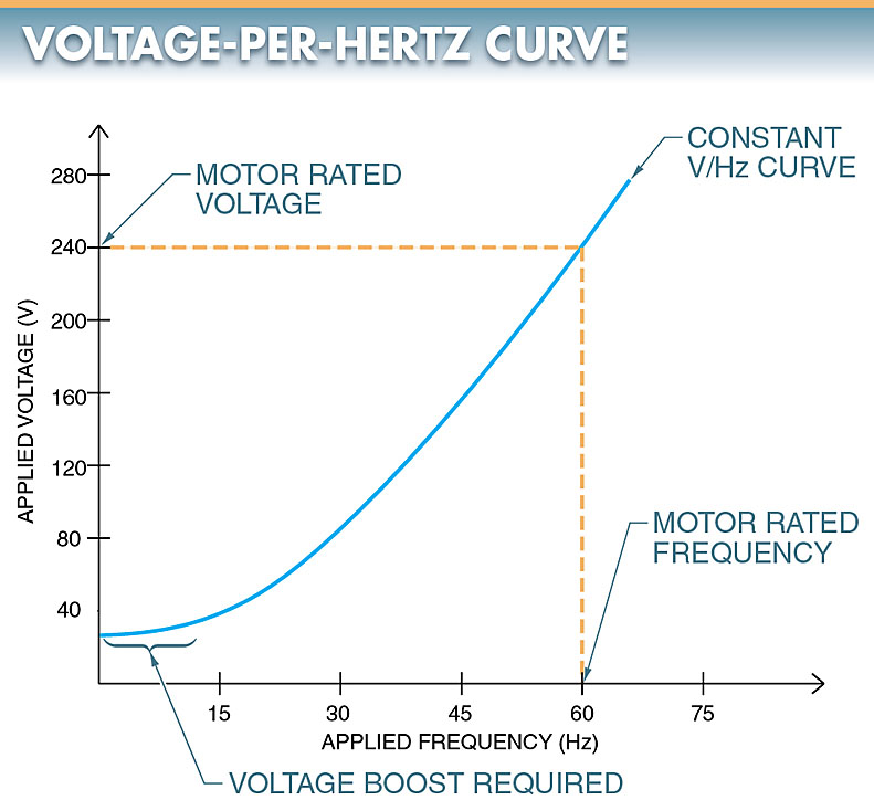
Figure 7. Below 15 Hz, the voltage applied to the motor stator may be boosted to compensate for the large power loss AC motors have at low speed.
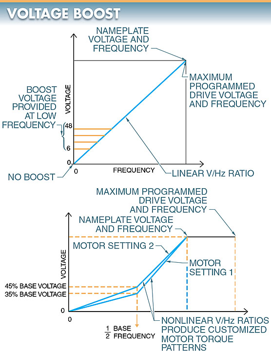
Figure 8. Motor drives can be programmed to apply a voltage boost at low motor speeds and to change the standard linear volts-per-hertz ratio to a nonlinear ratio.
Motor drives can also be programmed to change the standard linear volts-per-hertz ratio to a nonlinear ratio. A nonlinear ratio produces a customized motor torque pattern that is required by the load operating characteristics.
For example, a motor drive can be programmed for two nonlinear ratios that can be applied to fan or pump motors. Fans and pumps are normally classified as variable torque/variable horsepower (VT/VH) loads. VT/VH loads require varying torque and horsepower at different speeds.