The article covers various applications of digital circuits, including converting analog signals to digital pulses, using digital discs for information storage, and employing devices like encoders and decoders to translate between binary and decimal systems. It also highlights the role of digital circuits in technologies such as UPC scanning, logic probes for circuit testing, and the digitization of analog signals for storage and transmission.
Digital circuits are used for many reasons. For example, digital circuits convert ac sine waves to digital pulses, Figure 1. The ac signal is sampled. Various points are given digital values. These are later converted to a binary value.
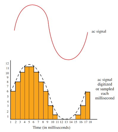
Figure 1. An ac signal being converted to digital pulses.
Figure 2 shows digital discs that have binary information recorded on their surface. A laser “reads” the information on the recording.
Another example of digital electronics use is the Universal Product Code (UPC). It is found on most items purchased today, Figure 3. The UPC is read by a laser (light). The laser improves inventory (item movement) control.
Some laser scanning systems contain a computer-generated voice that tells the operator and the customer what has been purchased and the price of the item.
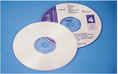
Figure 2. Digital discs.
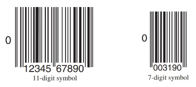
Figure 3. Universal Product Code symbols. (IBM)
Logic Probe
The basic piece of test equipment used for digital circuits is the logic probe. The logic probe indicates either a high or low signal using LEDs. Look at Figure 4.
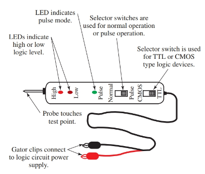
Figure 4. A typical logic probe for testing digital circuits.
The logic probe connects to the power supply of the circuit being tested. The red lead connects to the positive side of the power supply while the black (negative) lead connects to ground.
Most logic probes are equipped with a slide switch that allows you to select the logic family you will be testing, TTL or CMOS. The tip of the probe is touched to a pin on the chip or a connection point. The LED indicator lights to indicate a high or low logic value.
When both LEDs light there is either an invalid logic level voltage or the probe is not making good contact with the circuit. Each logic probe manufacturer uses a unique design. Therefore, the instruction book of a logic probe should always be checked before use.
Digital Encoders and Decoders
Most people have only learned the decimal number system. The digital system uses the binary numbering system, which is very different from the decimal system.
To make the binary numbering easily understandable to us, we use an electronic system to translate, or decode, the binary system into the decimal system. A device that makes this translation is called a decoder.
An example of a decoder is the 7448 chip. This chip converts a binary code to its decimal number equivalent on an LED seven-segment display. This instrument allows us to easily read the binary number as a decimal number.
The conversion process also works in reverse. A decimal number can be converted to a binary number through an encoder. Once the decimal number has been encoded to a binary number, it can be utilized in a digital system such as a computer.
There are also analog-to-digital and digital-to-analog converters. These devices can change analog information such as temperature to a digital number equivalent.
A digital multimeter is a good example of how analog information can be changed to digital information. When a voltage reading is taken from a circuit using a DMM, the input to the meter is an analog signal.
Inside the meter, the encoder changes the analog signal into a binary code. This code is then turned into the decimal number value that appears on the meter’s display.
Some circuits, such as the 7490 counter, are designed to convert electrical pulses into binary numbers. The counter advances by one each time the input receives an electrical pulse.
The counter can be connected to a decoder and an LED driver such as the 7448 to display the pulse count as a decimal number. See Figure 5.
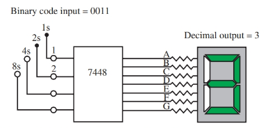
Figure 5. A 7448 chip will translate binary numbers to decimal numbers.
Digitized Analog Signals
A sound wave or linear voltage can be represented by a pattern of digital signals. There are many advantages to digitizing a sound wave pattern. A sound wave can be converted into a digital pattern using an analog-to-digital encoder. Each voltage level is represented by a binary code.
Figure 6 shows how the analog sound wave pattern might be represented by a series of binary numbers. The numbers can be transmitted by phone lines, satellites, microwave beams, etc. Once the sound pattern is encoded as a binary pattern, it can be transmitted faster than the time used to actually produce the sound. At its final destination, the digital pattern can be converted to an analog signal again.
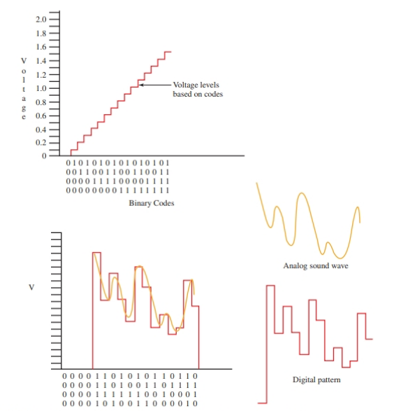
Figure 6. When using an analog-to-digital, or digital-to-analog converter, each binary code represents a different voltage value.
The digital wave pattern will be in sharp steps and must be smoothed out. This smoothing of the digital pattern is accomplished using a filter similar to the filter used on a power supply. Once the pattern is smoothed out, it will be a perfect match of the original signal.
The digitized pattern shown in Figure 6 looks a bit crude because it is based on a four-bit pattern. (Notice the bit patterns at the bottom of the graphs.) An actual digitized signal would use an 8-, a 16-, or a 32-bit encoder. The time increment between the binary codes would also be shortened.
The combined effect of a larger bit pattern, say 32 bits, and a shorter time period between binary code creates a digital pattern very close to the original analog pattern. Only a slight filtering action would be needed to smooth the digitized pattern to match the original analog sound pattern.
The digitizing of sound has made it possible to store sound in computer memory. Once stored, it can be played back later, or even manipulated to distort or enhance the sound. For example, an echo can easily be made from any original sound pattern, or the volume and tone of the pattern can be changed.
Digital Circuits Applications Key Takeaways
The applications of digital circuits are crucial in various modern technologies, ranging from converting analog signals to digital forms, to improving data storage, and enabling efficient communication. These circuits play a significant role in everyday devices like UPC scanners, digital meters, and audio systems, facilitating better control, faster processing, and enhanced functionality across numerous industries. Their ability to process and translate signals into binary code supports the foundation of digital systems, making them indispensable in today’s technological landscape.