In Figure 1 a single load connected to a source constitutes a simple circuit. The source is represented by a winding because all generators have windings in them.
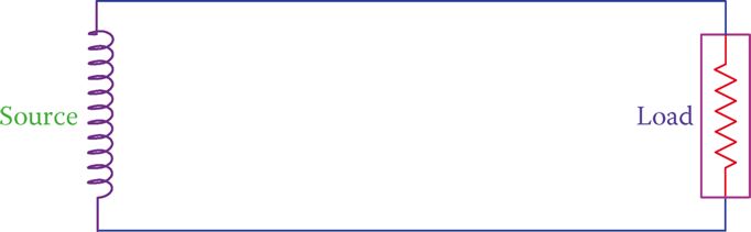
Figure 1 A single circuit consisting of a source and a load.
Figure 2 illustrates three of these assumed AC circuits near each other. Intentionally, the generators are shown forming a triangle, but at this time it is only a graphic layout.
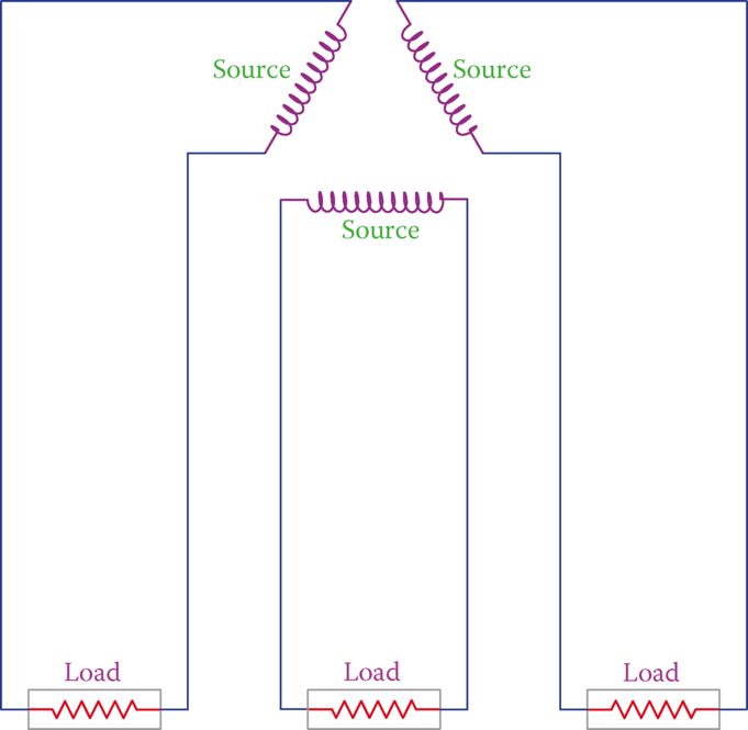
Figure 2 Three single-phase systems shown together.
For ease of reference, these systems are named A, B, and C. Suppose now that these three single-phase electric circuits are such that we can connect together the points that are near each other; that is, point A to B′, B to C′, and C to A′, as shown in Figure 3. If this can be done, then we may use only three wires for connection to the loads, instead of 6, provided that the loads permit this. This is shown in Figure 3, thus saving wire cost.

Figure 3 Saving in the number of wires used.
The arrangement on the right-hand side of Figure 3 can be rearranged to look as shown in Figure 4b, which is one of the ways a three-phase load can be connected to a three-phase source. The necessary condition to be able to connect the associated points in this circuit (A to B′, and so on) is that these points must have the same electric potential (the same voltage with respect to a reference) at any instant of time.
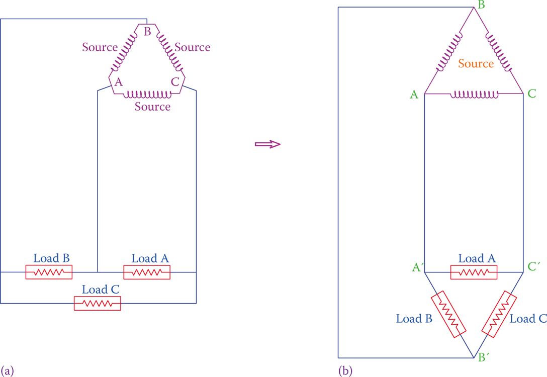
Figure 4 Common representation of a three-phase system. The three loads in (a) are shown as in (b).
If there is one winding, the generated electricity is a single phase but, if there are three windings as shown in Figure 5, then the generated electricity is three phase.
As you see in Figure 5, the three windings are placed at 120° from each other. This causes a phase difference between the three voltages that are generated. The reason is obvious; one of the windings sees the magnetic field before the other two, and again the second winding sees it before the third before everything is repeated.
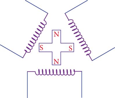
Figure 5 A simple representation of a three-phase generator, indicating the reason for the phase difference between the voltages in the three windings.
In other words, what happens to one winding in a given time happens to the other two windings with a delay that corresponds to 120° and 240° physical displacement.
As a result of the rotation of the magnetic field, the generated voltage in each winding has a sinusoidal form. For one cycle variation of the magnetic field, the generated voltages in each winding are illustrated in Figure 6.
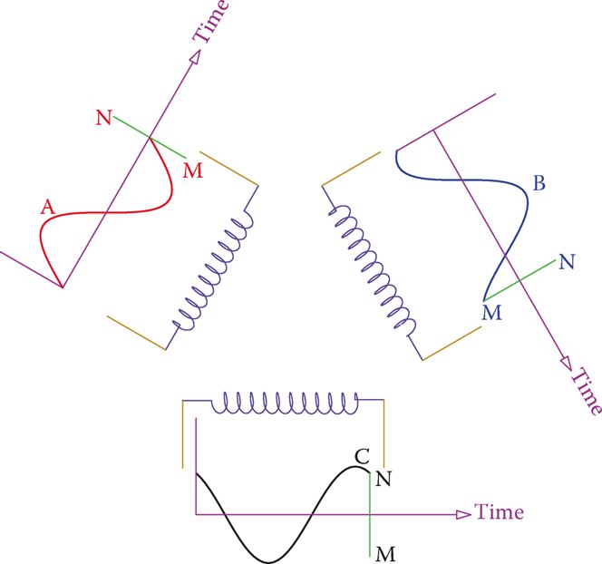
Figure 6 Individual waveform variation of the voltage in each winding for one cycle period.
When putting together, the three sinusoidal waveforms of a three-phase electricity system are shown in Figure 7. The three phases are addressed as phases A, B, and C, or phases 1, 2, and 3.
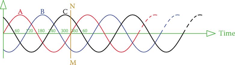
Figure 7 Waveforms of a three-phase system shown together on a common axis.
No matter what the three phases are called, their order is very important and must be respected. Observe that in Figure 7 phase A reaches its maximum before B and C. B reaches its maximum after 120°, and phase C reaches its maximum 120° after B (240° after A).
Also, notice that the vertical axis has no title because it can represent voltage or current. In Figure 7, line MN corresponds to the time for one full cycle and the variations of each phase are those shown in Figure 6.