
Definition: A voltmeter is a basic device used for the measurement of electric potential or voltage, in volts.
Voltmeter Working
The same basic meter movement that is used in an ammeter is also used to measure voltage. This is providing that the impressed voltage across the coil never exceeds 0.1 volt, as computed, for full-scale deflection.
To arrange the meter to measure higher voltages, multiplier resistors are placed in series with the meter movement coil using a switch. A meter similar to the meter that measured current is used. Refer to Figure 1.
Voltmeters are always connected in parallel with the device being measured.
Voltmeter Example
Follow the steps as the multipliers are computed so that the meter can measure voltages from 0–1 V, 0–10 V, 0–100 V, and 0–500 V.
Step 1.
Remember that no more than 0.1 volt is allowed across the meter coil at any time. Therefore, a resistor that will cause a voltage drop of 0.9 V must be placed in series with the meter if the meter is used to measure one volt.
Also, the meter only allows 0.001 A for full-scale deflection. This is the highest current allowed in the coil circuit. The multiplier resistor must produce a 0.9 V drop when 0.001 A flows through it.
\[{{R}_{M}}=\frac{E}{I}=\frac{0.9V}{0.001A}=900\Omega \]
Step 2.
To convert the 0–10 volt range, a resistor must be selected to produce a 9.9-volt drop.
\[{{R}_{M}}=\frac{E}{I}=\frac{9.9V}{0.001A}=9900\Omega \]
Step 3.
To convert the 0–100 volt range, a resistor must be selected to produce a 99.9 volt drop.
\[{{R}_{M}}=\frac{E}{I}=\frac{99.9V}{0.001A}=99,00\Omega \]
Step 4.
Finally, to use the 0–500 volt range, the resistor must cause a 499.9 volt drop.
\[{{R}_{M}}=\frac{E}{I}=\frac{499.9V}{0.001A}=499,00\Omega \]
Again, a switching device is used to select the correct multiple resistors for the range in use. Read the scale on the dial that corresponds to the range selected. The dial on a meter is generally referred to as the range selector switch.
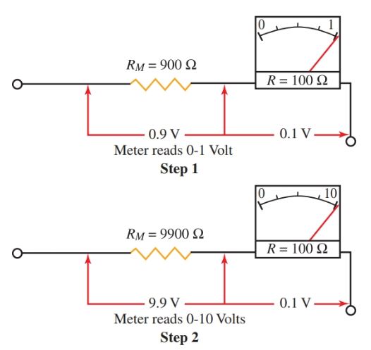
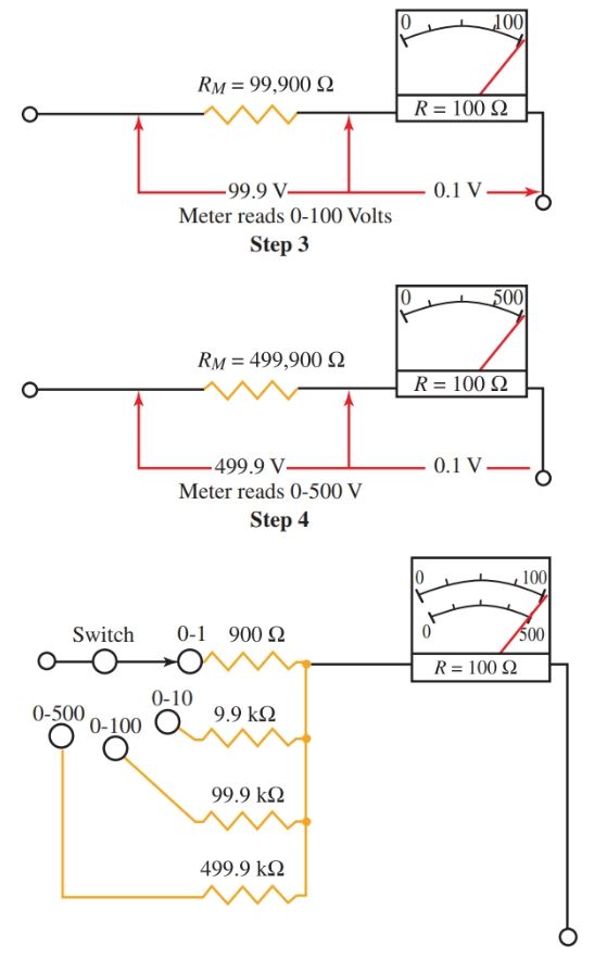
Figure 1.
Step 1—The multiplier causes an IR drop of 0.9 V.
Step 2—The multiplier causes an IR drop of 9.9 V.
Step 3—The multiplier causes an IR drop of 99.9 V.
Step 4—The multiplier causes an IR drop of 499.9 V.
Bottom—Basic setup of a voltmeter. A switch is added to select the range.
Caution
A voltmeter is always connected in parallel or across the circuit. To measure a voltage, the circuit does not have to be broken. See Figure 2.
As with the ammeter, when measuring an unknown voltage, always start measuring with the meter set on its highest range. Adjust downward to the proper range to avoid damaging the meter.
In addition, be sure that the leads are connected with the correct polarity. The black lead is negative and the red lead is positive
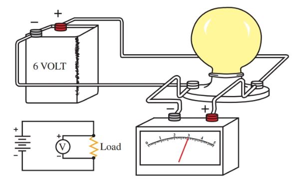
Figure 2. A voltmeter is connected in parallel with the device when taking a voltage reading.
Voltmeter Sensitivity
The sensitivity of a meter is a sign of quality. Ohms-per-volt is the unit for measuring sensitivity.
In Step 4 of the previous example, the total resistance of the meter and its multiplier resistance is:
\[\frac{499,900\Omega \left( in\text{ }{{R}_{M}} \right)+100\Omega \left( meter\text{ }resistance \right)}{500,000\Omega \left( total\text{ }resistance \right)}\]
The total amount of resistance in the 500 V range is equivalent to the following:
\[\frac{500,000\Omega }{500V}=100{}^{\Omega }/{}_{V}\]
Using Ohm’s law, I = E/R. The reciprocal of I is R/E. This is the same as the meter sensitivity. Therefore, the sensitivity is equal to the reciprocal of the current required for full scale deflection. For the meter used in the above example:
\[Sensitivity=\frac{1}{0.001\Omega \left( coil\text{ }resistance \right)}=1000{}^{\Omega }/{}_{V}\]
The sensitivity of a meter can be used to gauge meter quality. A quality meter has a sensitivity of at least 20,000 ohms/volt. Precision laboratory meters measure as high as 200,000 ohms/volt.
The accuracy of the meter is commonly expressed as a percentage, such as 1 percent. This means that the true value will be within one percent of the scale reading.
Another system of rating meters is the accuracy expressed as a percentage of full-scale reading. A meter may have a rating of ±0.05 percent or less. In general, the smaller the percentage, the higher the quality of the meter.
Loading a Circuit
When a voltmeter is connected across a circuit to measure a potential difference, it is in parallel with the load in the circuit. This situation can introduce errors in voltage measurement. In meters with low sensitivity, this is very common. It is very important to keep this in mind.
In Figure 3, two 10,000 ohm resistors form a voltage divider circuit across a ten-volt source. The voltage drops across both R1 and R2 are 5 volts each.
If a meter with a sensitivity of 1000 ohms/volt on the ten-volt range is used to measure the voltage across R1, the meter resistance will be in parallel with R1. For now, it is enough to know that the addition of this meter cuts the effective resistance of R1 in half. The combined resistance of the meter and R1 is equal to:
\[\begin{align} & \frac{{{R}_{1}}+{{R}_{M}}}{2}={{\operatorname{R}}_{effective}} \\ & \frac{10,000}{2}=5000\Omega \\\end{align}\]
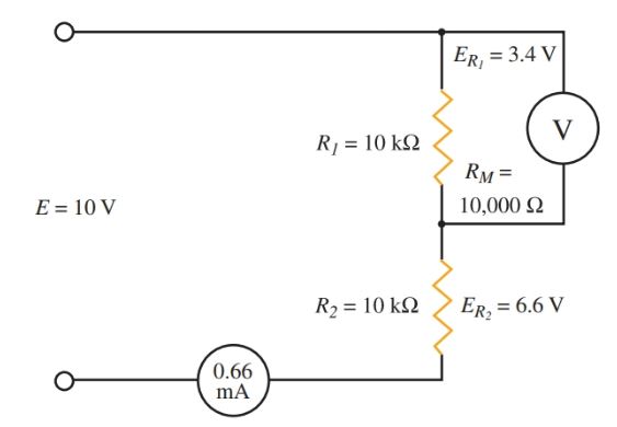
Figure 3. The meter loads the circuit and introduces an error in the voltage reading.
With the meter connected, the total circuit resistance becomes:
\[\begin{align} & {{\operatorname{R}}_{effective}}+{{R}_{2}}={{R}_{total}} \\ & 5000\Omega +10,000\Omega =15,000\Omega \\\end{align}\]
Using Ohm’s law, the current can be calculated at approximately 0.00067 amps. Using Ohm’s law again, ER1= 3.35 V and ER2= 6.7 V. The meter has caused an error of more than one volt due to its shunting effect.
To avoid an excess of errors resulting from this effect, a more sensitive meter should be used. In Figure 4, a 5000 ohms/voltmeter is used.
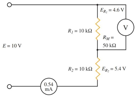
Figure 4. A sensitive meter gives more accurate readings.
In this case, the combined resistance of the meter and R1 equals 8333 ohms. The total circuit resistance is 18,300 ohms. Using Ohm’s law, I = 0.00055 amps, ER1= 4.6, and ER2 = 5.5 volts. An error of 0.4 volts still exists, but the increased sensitivity of the meter has reduced the error.
Even more costly meters, with a sensitivity of 20,000 ohms/volt, can reduce the error to an amount that would be barely noticed.
