The article provides an overview of solenoids, focusing on their types, construction, and functional components. It outlines various solenoid configurations and explains key construction elements such as armatures, shading coils, eddy current reduction, and the importance of air gaps in magnetic circuits.
A solenoid is an electric output device that converts electrical energy into a linear mechanical force. The magnetic attraction of a solenoid may be used to transmit force. Solenoids may be combined with an armature, which transmits the force created by the solenoid into useful work. An armature is the movable part of a solenoid.
Solenoid Types
Solenoids are configured in various ways for different applications and operating characteristics. The five solenoid types are clapper, bell-crank, horizontal- action, vertical-action, and plunger. See Figure 1.
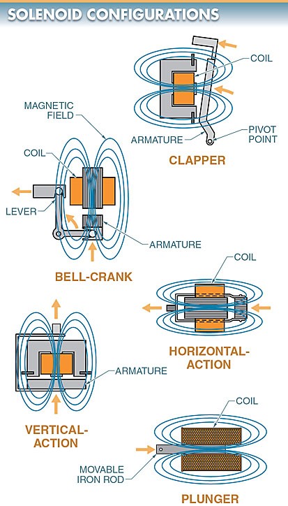
Figure 1. The five solenoid configurations are clapper, bell- crank, horizontal-action, vertical-action, and plunger solenoids.
A clapper solenoid has the armature hinged on a pivot point. As voltage is applied to the coil, the magnetic effect produced pulls the armature to a closed position so that it is picked up (sealed in).
A bell-crank solenoid uses a lever attached to the armature to transform the vertical action of the armature into a horizontal motion. The use of the lever allows the shock of the armature to be absorbed by the lever and not transmitted to the end of the lever. This is beneficial when a soft but firm motion is required in the controls.
A horizontal-action solenoid is a direct-action device. The movement of the armature moves the resultant force in a straight line. Horizontal-action solenoids are one of the most common solenoid configurations.
A vertical-action solenoid also uses a mechanical assembly but transmits the vertical action of the armature in a straight-line motion as the armature is picked up.
A plunger solenoid contains only a movable iron cylinder, or rod. A movable iron rod placed within the electrical coil tends to equalize or align itself within the coil when current passes through the coil. The current causes the rod to center itself so that the rod ends line up with the ends of the solenoid if the rod and solenoid are of equal length.
In a plunger solenoid, a spring is used to move the rod a short distance from its center in the coil. The rod moves against the spring tension to re-center itself in the coil when the current is turned on. The spring returns the rod to its off-center position when the current is turned off. The motion of the rod is used to operate any number of mechanical devices. See Figure 2.
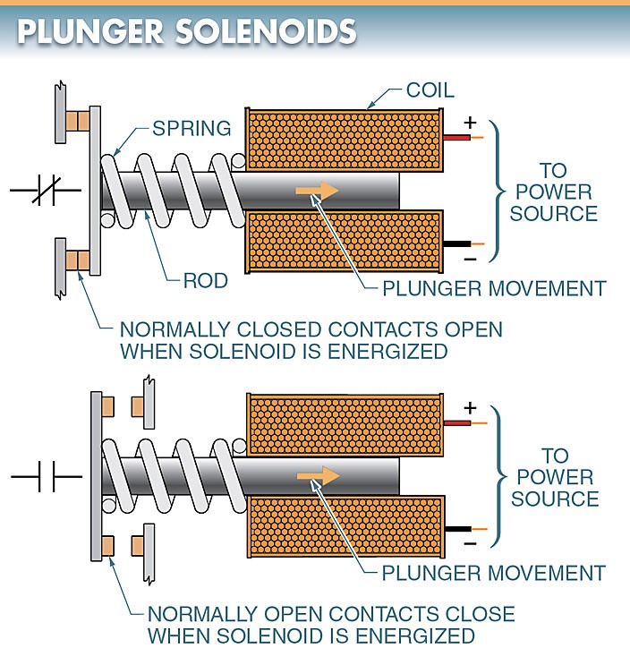
Figure 2. In a plunger solenoid, a spring is used to move the rod a short distance from its center in the coil. The rod moves against the spring tension to re-center itself when the current is turned on.
Solenoid Construction
Solenoids are constructed of many turns of wire wrapped around a magnetic laminate assembly. Passing electric current through the coil causes the armature to be pulled toward the coil. Devices may be attached to the solenoid to accomplish tasks like opening and closing contacts.
Eddy Current
Eddy current is unwanted current induced in the metal structure of a device due to the rate of change in the induced magnetic field. Strong eddy currents are generated in solid metal when used with alternating current.
In AC solenoids, the magnetic assembly and armature consist of a number of thin pieces of metal laminated together. The thin pieces of metal reduce the eddy current produced in the metal. See Figure 3. Eddy current is confined to each lamination, thus reducing the intensity of the magnetic effect and subsequent heat buildup.
For DC solenoids, a solid core is acceptable because the current is in one direction and continuous.
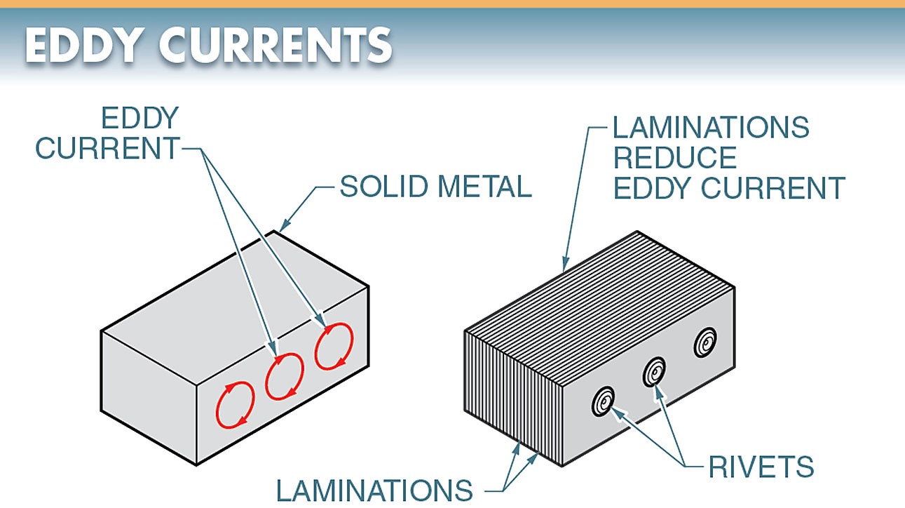
Figure 3. In AC solenoids, the magnetic assembly and armature consist of a number of thin pieces of metal laminated together.
Armature Air Gap
To prevent chattering, solenoids are designed so that the armature is attracted to its sealed-in position so that it completes the magnetic circuit as completely as possible. To ensure this, both the faces on the magnetic laminate assembly and those on the armature are machined to a very close tolerance.
As the coil is de-energized, some magnetic lines of force (residual magnetism) are always retained and could be enough to hold the armature in the sealed position. To eliminate this possibility, a small air gap is always left between the armature and the magnetic laminate assembly to break the magnetic field and allow the armature to drop away freely when de-energized. See Figure 4.
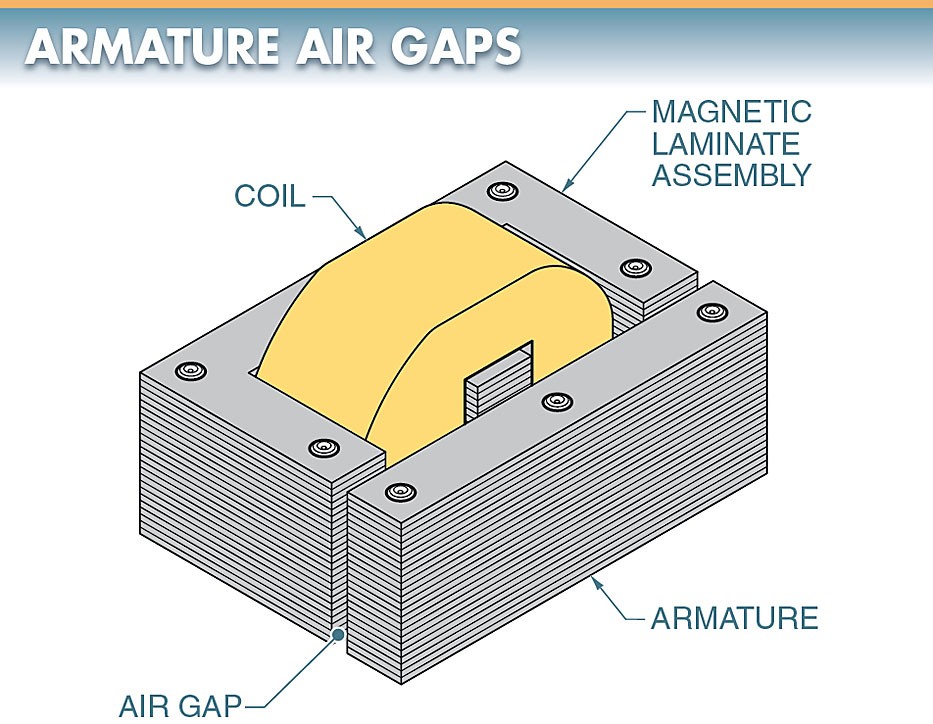
Figure 4. A small air gap is left in the magnetic laminate assembly to break the magnetic field and allow the armature to drop away freely after being de-energized.
Shading Coil
A shading coil is a single turn of conducting material (normally copper or aluminum) mounted on the face of the magnetic laminate assembly or armature. See Figure 5. A shading coil sets up an auxiliary magnetic field that helps hold in the armature as the main coil magnetic field drops to zero in an AC circuit.
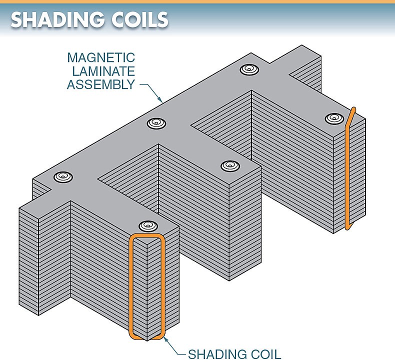
Figure 5. A shading coil sets up an auxiliary magnetic field that helps hold in the armature as the main coil magnetic field drops to zero in an AC circuit.
The magnetic field generated by alternating current periodically drops to zero. This makes the armature drop out or chatter. The attraction of the shading coil adds enough pull to the unit to keep the armature firmly seated. Without the shading coil, excessive noise, wear, and heat builds up on the armature faces, reducing the armature life expectancy.
Solenoid Types & Construction Key Takeaways
Understanding the various types and construction features of solenoids is essential for their effective application in electrical and mechanical systems. Their ability to convert electrical energy into controlled mechanical motion makes them vital components in a wide range of devices, including industrial automation, automotive systems, and household appliances, where precision, reliability, and efficiency are crucial.