The article discusses the analysis of a series RLC circuit, focusing on how voltage, current, impedance, and power are related when a resistor, inductor, and capacitor are connected in series. It also includes vector representations and example problems to illustrate concepts such as impedance calculation, phase angles, voltage distribution, and power factor.
In a series RLC circuit, the three basic elements are in series with each other, which means that they all have the same current. The formulation covers the general case of three types of the load being present in a circuit.
If any of the components is absent (usually, the inductor or the capacitor, not the resistor), then in calculations, the corresponding value for that element can be set to zero or the associated term deleted from the formulae.
Figure 1 illustrates a series RLC circuit. Note that the order the three components are shown is not important. Thus, in Figure 2 the two circuits are equivalent.
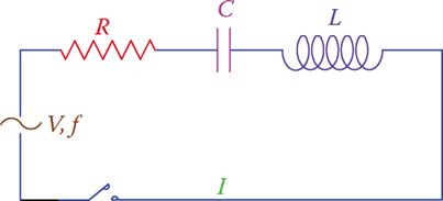
Figure 1 A series RLC circuit.
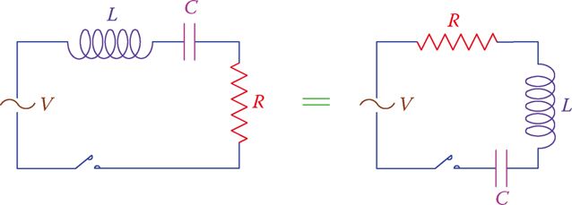
Figure 2 Two equivalent Series RLC circuits.
In tackling the circuit at hand, we need to know the relationship between the applied voltage and the current and the power consumption of the circuit, using all the knowledge that has been gained so far.
The simplest question with a series RLC circuits is finding the current in the circuit if the particulars of the loads and the applied voltage are given.
In the above circuit (Figure 1) V is the applied voltage, I is the common current for all the three elements, f is the frequency, and R, L, and C represent the values for resistance, inductance, and capacitance, respectively, of the three components in the circuit.
- You May Also Read: Parallel RLC Circuit: Analysis & Example Problems
The applied voltage in this circuit is divided between the three components. In this regard, the corresponding voltages across R, L, and C are denoted by VR, VL, and VC, respectively. Recall that each of these voltages follows the rules that we learned about the relationship between current and voltage in each component. That is,
The voltage across the resistor is in phase with the current, the voltage across the capacitor is lagging the current by 90° and the voltage across the inductor leading the current by 90°.
We now try to show these variables in the vector form. Because the three components have the same current, the most appropriate reference entity for showing the vectors is the circuit current I.
Figure 3 shows these vectors, irrespective of their numerical values (because we do not have any number of values given yet) but with the correct orientation. Nevertheless, remember that the scale for current and voltage can be different, whereas the scale for all identical values (voltages here) must be the same.
As can be seen in Figure 3, the voltage across R is in phase with the current, the voltage across L is leading the current, and the voltage across C is lagging the current. This implies that R, XC, and XL cannot be algebraically added together. Z is the vector sum of these three values. After their values have been determined, Z can be found.
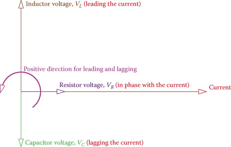
Figure 3 Vectors for the current and the three different voltages in the RLC series circuit.
Because a capacitor and an inductor have opposite effects, their corresponding vectors are opposite to each other, and, thus, their sum is represented by a number smaller than the larger value (XC – XL or XL – XC.
Figure 4 illustrates two cases, one when XC > XL and one when XC < XL). For similar values the value of Z obtained is the same for both cases.
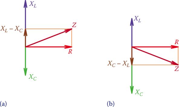
Figure 4 Relationship between R, XC, XL, and Z. (a) Positive phase angle. (b) Negative phase angle.
Using the Pythagorean Theorem the value of the impedance Z can be written as
\[\begin{matrix} Z=\sqrt{{{R}^{2}}+{{\left( {{X}_{L}}-{{X}_{C}} \right)}^{2}}} & {} & \left( 1 \right) \\\end{matrix}\]
(Note that it does not matter if one enters XL – XC or XC – XL).
Series RLC Example 1
In a series RLC, circuit R = 30 Ω, L = 15 mH, and C = 51 μF. If the source voltage and frequency are 12 V and 60 Hz, respectively, what is the current in the circuit?
Solution
$\begin{align} & {{X}_{L}}=2*3.14*60*0.015=5.655\Omega \\ & {{X}_{C}}=\frac{1}{2*3.14*60*0.000051}=5.655\Omega \\ & Z=\sqrt{{{30}^{2}}+{{\left( 52-5.655 \right)}^{2}}}=55.21\Omega \\ & I=\frac{12}{55.21}=217mA \\\end{align}$
Figure 5a is the same as Figure 4a. Because for the three components in series the current is the same, if all the values represented by the three sides of the triangle are multiplied by the current, then a similar triangle, as shown in Figure 5b, results. The sides of this triangle represent the voltages, since RI = VR, ZI = V, and so on.
Furthermore, if the sides of this new triangle are multiplied by I one more time, again a similar triangle results, which reflect the values for the various powers, as shown in Figure 5c.
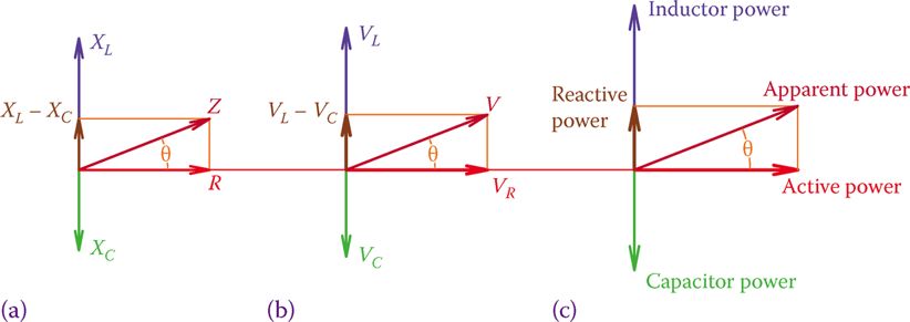
Figure 5 Similar triangles showing powers, voltages, and their relationships in a series RLC circuit. (a) Circuit resistance versus circuit impedance. (b) The voltage across resistance versus the applied voltage. (c) Circuit active power versus apparent power.
As can be understood from Figure 5b, the three voltage values VR, VL, and VC cannot be algebraically added together. These voltages are not in phase with each other and, hence, can only be added as vectors. In this respect, the relationship between VR, VL, and VC is
$\begin{matrix} V=\sqrt{V_{R}^{2}+{{\left( {{V}_{L}}-{{V}_{C}} \right)}^{2}}} & {} & \left( 2 \right) \\\end{matrix}$
Where V is the applied voltage. The second term under the radical is, in fact, the sum of the voltage across the inductor and the voltage across the capacitor, but, because these two voltages are 180° out of phase, their sum appears as a difference in values.
Power Factor in Series RLC Circuit
Figure 5a–c clearly shows that for a series RLC circuit the power factor can be found from one of the following relationships:
\[\begin{matrix} pf=\frac{R}{Z}=\frac{{{V}_{R}}}{V}=\frac{Active\text{ }Power}{Apparent\text{ }Power} & {} & \left( 3 \right) \\\end{matrix}\]
It is also easy to understand if the circuit is more inductive or more capacitive. This is reflected in the vector sum XL – XC and VL – VC (see Figure 4).
Series RLC Example 2
A series RLC circuit consists of a 20 Ω resistor, a 51 μF capacitor, and a 25 mH inductor. If the source frequency is 50 Hz, and the circuit current is 350 mA, what is the applied voltage?
Solution
$\begin{align} & R=20\Omega \\ & {{X}_{L}}=2*3.14*50*0.025=7.85\Omega \\ & {{X}_{C}}=\frac{1}{2*3.14*50*0.000051}=62.445\Omega \\ & Z=\sqrt{{{20}^{2}}+{{\left( 7.85-62.445 \right)}^{2}}}=58.15\Omega \\ & V=IZ=58.15*0.35=20V \\\end{align}$
In a series RLC circuit the voltages across the three components are not in phase with each other.
Series RLC Example 3
If the applied voltage to the circuit of Example 2 is 12 V, what is the voltage across the capacitor?
Solution
In Example 2 the applied voltage was 20 V. The distribution of this voltage among the three components is as follows:
$\begin{align} & {{V}_{R}}=20*0.35=7V \\ & {{V}_{C}}=62.445*0.35=21.85V \\ & {{V}_{L}}=7.85*0.35=2.75V \\\end{align}$
In the current case, when the applied voltage is 12 V (i.e., 0.6× the previous case) because nothing has changed in the circuit, the current will be accordingly smaller by 0.6×. As a result, all voltages will be 0.6× smaller. The voltage across the capacitor, therefore, is
${{V}_{C}}=21.85*0.6=13.1V$
You see that it is not necessary always to do repeat all the calculation. Also, note that the voltage across the capacitor is larger than the applied voltage of 12 V. This is always possible, and we do not expect all the voltages to be smaller than the applied voltage.
Series RLC Example 4
In the circuit of Example 2, what is the phase angle between the voltage and the current?
Solution
The answer can be found by first finding the power factor from any of the relationships in Equation 3. The values of R and Z are readily available and are the best choice.
$\begin{align} & pf=\frac{R}{Z}=\frac{20}{58.15}=0.344 \\ & Phase\text{ }Angle={{\cos }^{-1}}\left( 0.344 \right)={{70}^{o}} \\\end{align}$
Knowing only the value of the phase angle to be 70° is not sufficient, and we need to express if the circuit is leading or lagging (i.e., if the current leads the voltage or it lags the voltage). This can be judged based on the values of XC and XL. If XC > XL, then the current leads the voltage and if XC < XL, the current lags the voltage.
Series RLC Example 5
When a series RLC circuit is subject to 48 V, VR is 15 V, and VL is 22 V. What is the voltage across the capacitor?
Solution
According to Equation 2,
$V=\sqrt{V_{R}^{2}+{{\left( {{V}_{L}}-{{V}_{C}} \right)}^{2}}}=48V$
Because ${{V}_{R}}=15V,{{\left( {{V}_{L}}-{{V}_{C}} \right)}^{2}}$ is determined as (directly from Equation 2)
${{\left( {{V}_{L}}-{{V}_{C}} \right)}^{2}}={{V}^{2}}-V_{R}^{2}={{48}^{2}}-{{15}^{2}}=2079={{45.6}^{2}}$
Attention must be paid here in calculating (VL – VC) because there are two answers for it. This also reflects the fact that, when squared, both (VL – VC) and (VC – VL) lead to the same result. Thus,
$\pm \left( {{V}_{L}}-{{V}_{C}} \right)=45.6V$
Having VL = 22 V leads to only one acceptable value. (The other value is negative and is not acceptable.) Hence, the value for VC is
${{V}_{C}}=67.6V$
One of the characteristics of a series RLC circuit is that the voltage between two points can be higher than the applied voltage.
Series RLC Circuit Key Takeaways
Understanding the behavior of a series RLC circuit is fundamental in analyzing how electrical energy is managed and transferred in AC systems. The detailed exploration of voltage, current, impedance, phase relationships, and power factor provides the foundational knowledge necessary for designing and troubleshooting real-world applications such as radio transmitters, signal filters, tuning circuits, and power distribution systems. These concepts allow engineers and technicians to optimize circuit performance, ensure efficient energy usage, and prevent power losses due to phase mismatches. Moreover, the use of vector analysis and impedance calculations enables precise control of voltage and current distribution, which is vital in applications where signal clarity, resonance, or power factor correction is critical.