In parallel RLC circuit the three basic components are in parallel with each other, and, therefore, all are subject to the same voltage. The current for each branch, however, depends on the impedance of the branch and can be individually determined by employing Ohm’s law.
For a parallel RLC circuit, the voltage is common for all the three types of components because it is the same voltage that is applied to each component. Nevertheless, the currents in the three branches are not in phase with each other. This means that the currents in the three branches do not simultaneously reach their peak values or zero values.
Hence, the total current cannot be determined by algebraically adding the individual values of the currents in the resistor, inductor, and capacitor.
A parallel RLC circuit is shown in Figure 1. As in the case of series RLC circuits, we need to find the total current and the power consumption for the whole circuit or for each individual branch.
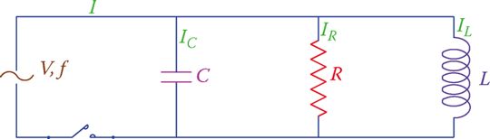
Figure 1 Schematic of parallel RLC circuits.
For this circuit the voltage applied to each component in each branch is the same. Therefore, the current in each component can be found from dividing the voltage by the branch impedance. Then the currents can be added together.
However, because the currents in the three components are not in phase with each other (they do not reach their maximum and minimum values at the same time), they cannot be algebraically added together and must be added in vector form.
- You May Also Read: Series RLC Circuit: Analysis & Example Problems
Figure 1 illustrates the vector representation of the three currents in a typical parallel RLC circuit. It shows that the current in the resistor is in phase with the applied voltage, the current in the capacitor leads the applied voltage (remember ICE) and the current in the inductor lags the voltage (remember ELI).
Furthermore, note that for this vector representation of the currents and voltage in a parallel RLC circuit, because the voltage is the common variable for all branches, you start by drawing the vector for the voltage as the reference vector. (In series RLC circuit you started this process by drawing the vector for the current.)
To find the total current in a parallel RLC circuit, one needs to find the vector sum of the currents in R, L, and C.
Because the current in the inductor and the current in the capacitor are 180° out of phase, in adding them together their values are subtracted from each other. Thus, the relationship for the total current of the circuit, I, and the individual component currents IR, IL, and IC is
$\begin{matrix} I={{\sqrt{I_{R}^{2}+\left( {{I}_{L}}-{{I}_{C}} \right)}}^{2}} & {} & \left( 1 \right) \\\end{matrix}$
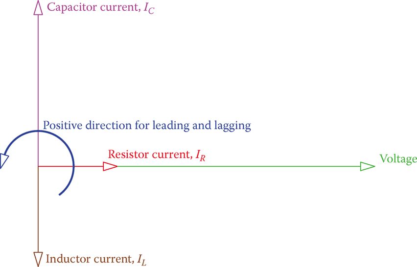
Figure 2 Vectors for the voltage and the three different currents in the RLC parallel circuit.
Parallel RLC Circuit Example 1
In the circuit shown in Figure 3 the current is 1.8 A. If the current through the capacitor is 1.5 A, find the applied voltage and the resistance of the resistor.
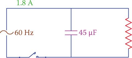
Figure 3 Circuit corresponding to Example 1.
Solution
For 60 Hz frequency, the reactance of the capacitor is
\[{{X}_{C}}=\frac{1}{2*3.14*60*0.000045}=59\Omega \]
Thus, the applied voltage is
$59*1.5=88.5V$
Because this circuit has no inductor, the value of L in Equation 1 is set to zero and the result is
$I=\sqrt{I_{R}^{2}+I_{C}^{2}}$
Which leads to
\[{{I}_{R}}=\sqrt{{{1.8}^{2}}-{{1.5}^{2}}}=0.995=1A\]
And the resistance of the resistor is
$88.5\div 1=88.5\Omega $
If in Equation 1, the values for IR, IL, and IC are replaced by $\frac{V}{R},\frac{V}{{{X}_{L}}}$ and I is written as the ratio of the applied voltage to the circuit impedance Z, we have
\[\frac{V}{Z}=\sqrt{{{\left( \frac{V}{R} \right)}^{2}}+{{\left( \frac{V}{{{X}_{L}}} \right)}^{2}}}\]
By omitting V from both sides the relationship between Z and R, L, and C can be found then as
\[\begin{matrix} \frac{1}{Z}=\sqrt{{{\left( \frac{1}{R} \right)}^{2}}+{{\left( \frac{1}{{{X}_{L}}}-\frac{1}{{{X}_{C}}} \right)}^{2}}} & {} & \left( 2 \right) \\\end{matrix}\]
Equation 2 can be used to find the equivalent impedance of the three components in parallel. The circuit current can also be found this way by dividing the applied voltage by Z or by directly multiplying $\frac{1}{Z}$ by the applied voltage.
Parallel RLC Circuit Example 2
In the circuit shown in Figure 4, R = 55 Ω, L = 0.08 H, and C = 1 μF, find the impedance of the circuit and the applied voltage.
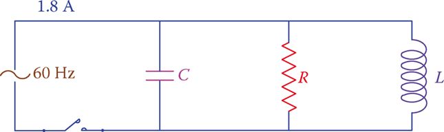
Figure 4 Circuit for Example 2.
Solution
$\begin{align} & {{X}_{L}}=2*3.14*60*0.08=30.16\Omega \\ & {{X}_{C}}=\frac{1}{2*3.14*60*0.000001}=26.5\Omega \\ & \frac{1}{Z}=\sqrt{{{\left( \frac{1}{55} \right)}^{2}}+{{\left( \frac{1}{55}-\frac{1}{26.5} \right)}^{2}}}=\frac{1}{53.33} \\ & Z=53.33\Omega \\\end{align}$
Applied voltage = V = ZI = (53.33) (1.8) = 96 V.
Equation 2 also implies that the value for Z is smaller than R for parallel RLC circuits. A vector representation of IR, IL, IC, and I is shown in Figure 5, which also shows the powers in the three components and the apparent power.
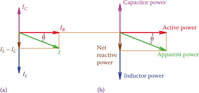
Figure 5 Vectors for (a) currents and (b) powers in parallel RLC circuits.
Reactive power is the vector sum of the inductive and capacitive powers. Depending on if inductive power (QL) or the capacitive power (QC) is larger the vectors for I and the apparent power S fall below or above the horizontal reference. The former implies that the current leads the voltage and the latter denotes that the current lags the voltage.
Because in practice the majority of applications (including home and industrial circuits) are parallel circuits, any circuit is categorized to be leading or lagging. If in a circuit the current leads the voltage, the circuit is said to be leading; if the current lags the voltage, the circuit is said to be lagging.
Power Factor in Parallel RLC Circuits
Figure 5 shows a lagging circuit. In practice, most of the circuits are lagging because of the presence of electric motors, unless the effects of electric motors are compensated by inserting capacitors that introduce capacitive power to a circuit (see power factor correction). The power factor in a parallel RLC circuit is determined from
\[\begin{matrix} pf=\frac{Z}{R}=\frac{{{I}_{R}}}{I}=\frac{Active\text{ }Power}{Apparent\text{ }Power} & {} & \left( 3 \right) \\\end{matrix}\]
Note that the power factor by itself is not sufficient to describe a circuit. It has to be accompanied by the statement for leading or lagging. A circuit may have the same power factor in two cases, either leading or lagging. Sometimes the leading or lagging is attributed to the power factor. For example, one may say a circuit has a leading power factor of 0.90.
Parallel RLC Circuit Example 3
In the circuit shown in Figure 6, the total current is 150 mA and the current through the inductor is 100 mA. Determine what the applied voltage is. Also, knowing that the frequency is 50 Hz, find the value of L.
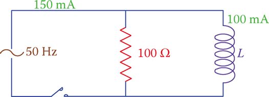
Figure 6 Circuit of Example 3.
Solution
The applied voltage can be found by multiplying the resistor current by 100 Ω. Having only a resistor and an inductor in this circuit Equation 1 leads to
$\begin{align} & {{I}_{R}}=\sqrt{{{I}^{2}}-I_{L}^{2}}=\sqrt{{{150}^{2}}-{{100}^{2}}}=0.1118A \\ & V=100*0.0008=11.18V \\ & {{X}_{L}}=11.18\div 0.100=111.8\Omega \\ & L=\frac{{{X}_{L}}}{2\pi f}=\frac{111.8}{2\pi *50}=35.6mH \\\end{align}$
In a parallel AC circuit, if the current leads the voltage, the circuit is said to be leading; if the current lags, the voltage the circuit is said to be lagging.
Parallel RLC Circuit Key Takeaways
Understanding parallel RLC circuit is crucial because of their widespread applications in real-world electrical and electronic systems. These circuits, characterized by having resistors, inductors, and capacitors connected in parallel, are essential in designing and analyzing power distribution networks, radio frequency tuning systems, and signal filtering applications. The unique behavior of voltage being common across all components while currents vary and remain out of phase necessitates vector analysis for accurate current and impedance calculations.