Norton’s theorem is used for simplifying a network in terms of currents instead of voltages. This theorem can be used with either single-source or multiple-source circuits. In certain cases, analyzing the division of currents may be easier than voltage analysis.
Norton’s theorem simplifies a resistive network and represents it with a Norton equivalent current source (IN) in parallel with an equivalent Norton resistance (RN), as shown in Figure 1.
The basis of Norton’s theorem is the use of a current source to supply a total load current that is divided among parallel branches.
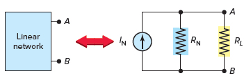
Figure 1 Norton equivalent circuit.
Norton’s Equivalent Circuit
As with similar theorems, certain steps have to be performed to arrive at an equivalent circuit. The following steps are used to convert a resistive network into its Norton equivalent circuit:
- Calculate the Norton equivalent current source. This is equal to the current that would flow between terminals A and B if the load resistor was removed and replaced with a short circuit.
- Calculate the Norton equivalent resistance. This is equal to the resistance between terminals A and B when the voltage source is removed and replaced with a short circuit.
Norton’s Equivalent Circuit Example 1
Problem: Derive the Norton equivalent circuit for the simple resistive network circuit shown in Figure 2. Calculate the load current and voltage for the 6-Ω load resistor RL. Repeat the calculations for a load resistor of 3 Ω.
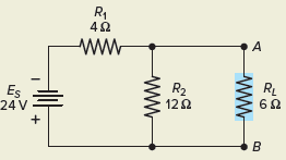
Figure 2 Circuit for Example 1.
Solution:
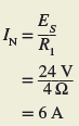
Step 1. Short-circuit the load terminals A–B as shown in Figure 3. Calculate the resulting current flow. This is the value of the Norton equivalent current source IN. Note that the short circuit across terminals A–B short-circuits both RL and the parallel R2. Then the only resistance in the circuit is R1 in series with the voltage source.
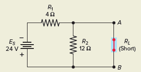
Figure 3 Circuit for step 1.
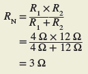
Step 2. The Norton equivalent resistance (RN) is equal to the resistance between terminals A and B with the load removed and the voltage source replaced with a short circuit, as shown in Figure 4. The resistance seen looking back into the circuit from terminals A-B is then R1 in parallel with R2.
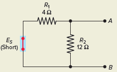
Figure 4 Circuit for step 2.
Step 3. The resultant Norton equivalent circuit is shown in Figure 5. It consists of a 6-A current source (IN) in parallel with a 3-Ω resistance (RN).
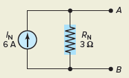
Figure 5 Norton equivalent circuit.
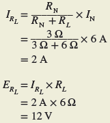
Step 4. To calculate IRL and ERL, connect the load resistor to the equivalent Norton circuit, as shown in Figure 6. The current source still delivers 6 A, but now that current is divided between the two branches of RN and RL. The load current can be calculated using the current divider rule, and the load voltage can be calculated using Ohm’s law.
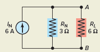
Figure 6 Circuit for step 4.
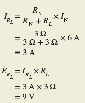
Step 5. When the value of RL is changed, the values of IN and RN remain the same. Therefore the load current and voltage for a 3-Ω load can be determined as follows without recalculating the entire circuit.
Norton’s Equivalent Circuit Example 2
Problem: Derive the Norton equivalent circuit for resistive network shown in Figure 7.
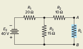
Figure 7 Circuit for Example 2.
Solution:
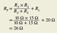
Step 1. Short-circuit the load, as shown in Figure 8, to determine the Norton equivalent current. Note that the short circuit current IN in this example is a branch current, not the main line current. Resistors R2 and R3 are now in parallel so the total resistance seen by the voltage source is
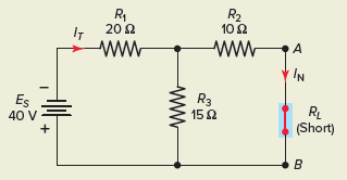
Figure 8 Circuit for step 1.
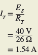
The total current is then
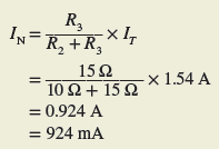
The Norton equivalent current is then found by using the current divider rule:
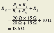
Step 2. Short-circuit the voltage source, as shown in Figure 9 to find the Norton equivalent resistance of the circuit. R1 and R3 are now in parallel, and R2 is in series with this parallel combination.
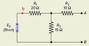
Figure 9 Circuit for step 2.
Step 3. The Norton equivalent circuit can then be drawn as shown in Figure 10.
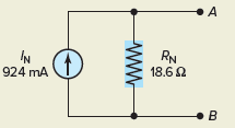
Figure 10 Norton equivalent circuit.
The Norton equivalent circuit may also be determined directly from the Thevenin equivalent circuit, and vice versa. Figure 11 shows the relationship between the two circuits. The following formulas can be used to convert from one equivalent circuit to the other:
From Thevenin to Norton

From Norton to Thevenin
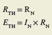
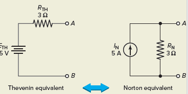
Figure 11 Norton–Thevenin conversions.
