For three-phase electricity transformation, it is possible to use three separate but similar single-phase transformers, or a three-phase transformer. A three-phase transformer is more compact and more efficient. The single core in a three-phase transformer can have various forms by combining the cores of single-phase transformers. Figure 1 shows the more common core forms.
In practice, however, in addition to the basic structure, there are other concerns to be considered in order to increase the efficiency and protection of a transformer. A cutaway of a medium-sized, three-phase transformer is shown in Figure 2.
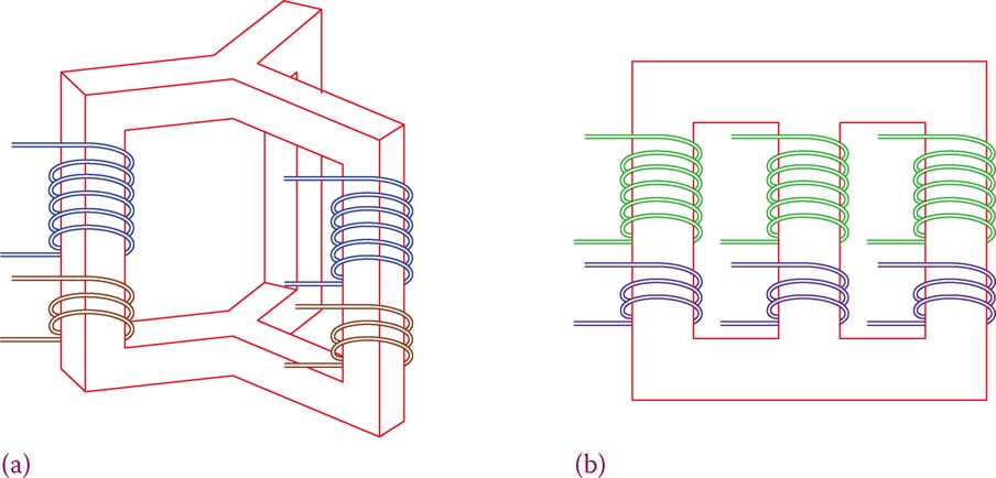
Figure 1 Basic structure of the three-phase transformer. Transformer core structure can be as in (a) or in (b).
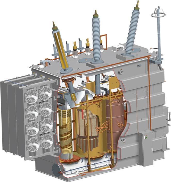
Figure 2 Construction of a three-phase transformer.
In a three-phase transformer the three primary windings are connected to the supply voltage as a three-phase load for the power supply circuit; so, they can have a star or delta (Y or Δ) connection.
Independent of how the primary side is connected, the secondary windings can be connected together forming either a star or a delta. This implies that there are four ways that a three-phase transformer can be used in a circuit.
The four ways are referred to as delta-delta, delta-star, star-delta, and star-star; these are shown in Figure 3. Thus, the voltage ratio not only depends on the turn ratio of the windings but also on what way the connections are made.
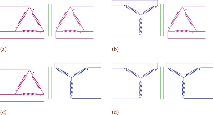
Figure 3 Four different connections for primary and secondary windings connection in a three-phase transformer. (a) Delta – delta. (b) Wye – delta. (c) Delta – wye. (d) Wye – wye.
The choice of the connection depends on the application. A delta-delta connection is used in many industrial (factories and manufacturing) applications. In electricity transmission that might not be the best choice, depending on various other factors. Grounding for faults and the existence or excitation of harmonics are among these factors.
If the higher voltage has delta connection and the lower voltage side is connected in wye and has a ground, this is referred to delta high-grounded wye low. This is the standard connection used by utilities for transmission and distribution.
Some (large) transformers in power generation and distribution have auxiliary windings in addition to the main windings. This smaller winding is referred to as tertiary. In the case that the two main windings are wye connected because both provide a reference point for grounding, the tertiary winding is delta connected, and its purpose is to provide a path for the third harmonics.
Tertiary winding: Auxiliary winding in a three-phase transformer used for providing a grounding point or for making a path for the flow of certain currents, depending on the case.
The purpose of the tertiary winding can be for providing a neutral point for grounding; for example, when both main windings are delta connected. A Y-connected tertiary then provides a reference for grounding. Another way of generating a neutral point for grounding is using a zigzag transformer.
Zigzag transformer: Special three-phase transformer in which the primary and secondary windings have the same number of turns and are combined in a particular way such that they cancel the magnetic effect of each other. It can be used for various purposes including fault detection.
In the two cases where both windings are connected the same way, the voltage ratio can be used, similar to the case of a single-phase transformer.
In the other two cases, the situation is different. Each winding in the primary is matched with a winding in the secondary. Figure 4 helps to understand this fact. In addition to the change in voltage ratio for these cases, there is a phase difference between the primary and secondary voltages. There is a 30° phase shift for star-delta and delta-star combination.
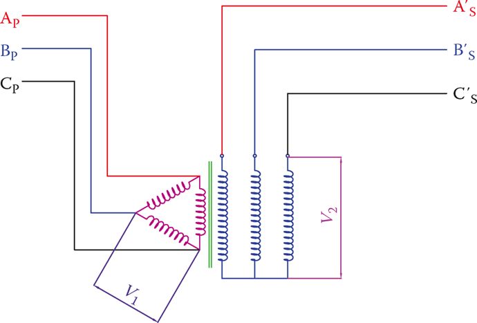
Figure 4 The voltage relationship between windings in a three-phase transformer.
The current can always be found from the power relationships. The key issue is that for an ideal transformer the load on the secondary of a transformer determines the power that the transformer must deliver. In real transformers, the power loss also must be considered.
In three-phase transformers, voltage ratio depends not only on the turns ratio but also on the way (wye or delta) the primary and secondary windings are connected to their circuits. For star-delta and delta-star combination in three-phase transformers, there is a 30° phase shift between the two sides of a transformer.
In practice, to show the connection configuration of three-phase transformers, a symbol as shown in Figure 5 is used. This figure shows that the primary is delta connected and the secondary is wye connected and is grounded at neutral.
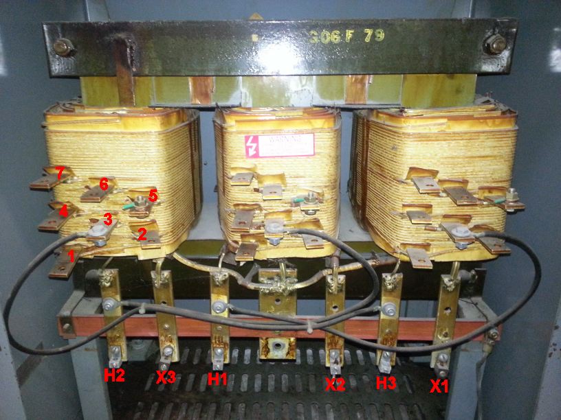
For three-phase transformers, high voltage terminals are marked by H1, H2, and H3, and the other ones are marked by X1, X2, and X3. H′ and X′ may be used for indicating the other side of each winding.
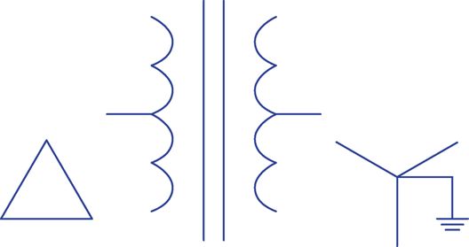
Figure 5 Symbol for showing three-phase transformer and connection configuration.
When connecting three-phase transformers or when connecting three single-phase transformers to form a three-phase transformer, special care must be taken in the correct order of connecting the 12 available terminals.
Any connection made in the wrong order can lead to damaging the transformer and other equipment. An identification of various terminals and a sketch of how they must be connected, based on the required connection is of paramount importance.
Example 1
The turns ratio in a step-up transformer is 1:2.65. The primary line voltage is 4160 V and the primary windings are connected in Δ. Determine the secondary line voltage (1) if the secondary windings are also connected in Δ and (2) if the secondary windings are connected in Y.
Solution
1. Because the primary and secondary windings have the same type of connection, the secondary line voltage is multiplied by the turns ratio:
$Secondary\text{ }Line\text{ }Voltage=4160\times 2.65=11,024V$
2. The voltage between the two ends of each secondary winding is 2.65× of that of the primary, i.e., 11,024 V. Line voltage is the voltage between each two of phase lines, which is $\sqrt{3}$ times larger. Thus, the line voltage for this connection is
$11,024\times 1.73=19,071V$
Example 2
The primary winding of a transformer is Y connected to 11,000 V line. If the secondary winding is Δ connected, and the turns ratio in the transformer is 15:1, what is the secondary line voltage?
Solution
Because the primary is Y connected, the voltage affecting each winding is $\sqrt{3}$ times smaller. This smaller voltage is transformed and reduced by the turns ratio.
$\begin{align}& \frac{11,000}{\sqrt{3}}=6350.85V \\& \frac{6350.85}{15}=423.4V \\\end{align}$
Thus, the secondary line voltage is 423.4 V.
Example 3
A three-phase load takes 25 A from the secondary of a step-down transformer supplying 418 V line voltage. If the transformer secondary windings are delta connected and its primary windings are Y connected, find the current in the primary of this transformer. The transformer turns ratio is 20:1.
Solution
The nominal apparent power for the load is
$\sqrt{3}\times 418\times 25=18,100VA$
Because the secondary is delta connected and the primary is Y connected, the line voltage in the primary is
$\sqrt{3}\times 418\times 20=14,480V$
Because for three-phase circuits$apparent\text{ }power=S=\sqrt{3}{{V}_{L}}{{I}_{L}}$, the current in the primary circuit due to this load is
\[\frac{18,100}{\sqrt{3}\times 14,480}=0.72A\]
Example 4
A three-phase delta-delta transformer is used to convert 14,400 to 380 v. Find the turns ratio.
Solution
Because nothing is mentioned about the two given voltages, they are the line voltages of the primary and secondary sides. Because both windings are delta connected, the ratio between the line voltages can directly determine the required turns ratio.
\[Turns\text{ }Ratio=a=\frac{14,400}{380}=37.9\]
