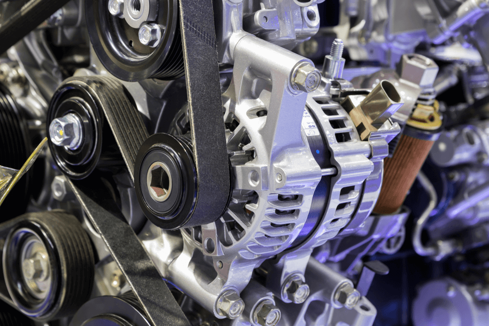
The purpose of an alternator is to change the spinning motion of the alternator pulley (mechanical energy) into electrical energy. See Figure 2. The components of a typical alternator are shown in Figure 3. They include:
Rotor assembly—field windings, claw poles, rotor shaft, and slip rings.
Stator assembly—three stator windings, stator core, and output wires.
Brush assembly—brush housing, brushes, brush springs, and brush wires.
Rectifier assembly—diodes, heat sink or diode plate, and electric terminals.
Fan and pulley assembly—fan, spacer, pulley, lock washer, and pulley nut.
Housing—drive end frame, slip ring end frame, and end bolts.
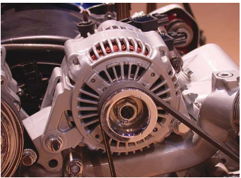
Figure 2. The alternator produces AC electricity, which is then converted to DC for use by various automotive systems.
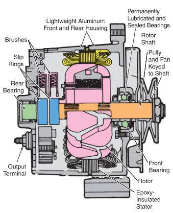
Figure 3. This cutaway of an alternator shows its major parts. (Chevrolet)
Rotor and Stator Assemblies
The two main parts of a simplified alternator are the rotor and stator. See Figure 4. The rotor is a magnetic field winding mounted on a shaft, as shown in Figure 5. The rotor shaft is mounted on roller or needle bearings so the rotor can turn freely. The alternator belt turns the rotor, making the field spin.
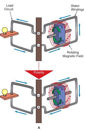
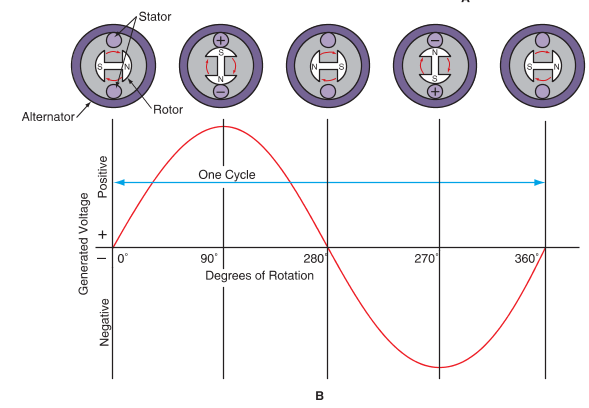
Figure 4. In an alternator, the rotor spins inside the stator.
A—The spinning magnetic field induces current into the stationary windings of the stator.
B—As the north and south poles of the spinning field cut across the stationary windings, an output current is generated. The sine wave represents the reversing polarity or reversing current flow
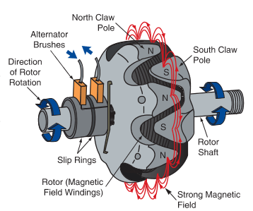
Figure 5. The rotor has claw poles that surround its windings. This produces a strong magnetic field that induces current into the stator. Note the north and south poles of the claws.
The alternator bearings are normally packed with grease. The front bearing is frequently held in place with a small plate and screws. The rear bearing is usually press-fit into place.
The stator is a stationary set of windings that surrounds the rotor. See Figure 6. The stator serves as the output winding of the alternator. A typical rotor and stator are shown in Figure 7. When the rotor spins, its strong magnetic field cuts across the stator windings, inducing a current in them. If the stator windings are connected to a load, the load will operate.
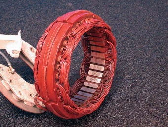
Figure 6. The stator consists of a stationary set of windings that surrounds the rotor.
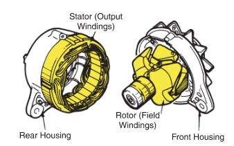
Figure 7. The spinning rotor mounts inside the stator. The stator produces high output current for the alternator.
The stator usually consists of three coils wrapped around an iron core. The iron core increases the field strength so more current can be induced into the stator by the rotor field.
Two types of stators are shown in Figure 8. In a Y-type stator, the wire ends from the stator windings are connected to a neutral junction so that the circuit looks like the letter “Y.” A Y-type stator provides good current output at low engine speeds. In a delta-type stator, the stator wires are connected end-to-end. With no neutral junction, two circuit paths are formed between the diodes during each phase, or AC voltage output from the alternator. Delta-type stators are used in high-output alternators.
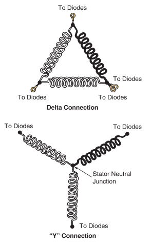
Figure 8. Two types of stators.
Brush Assembly
The alternator brushes ride on slip rings to make a sliding electrical connection. See Figure 9. The slip rings are mounted on the rotor shaft to feed a low current into the rotor windings. Refer again to Figure 5. Each end of the field winding connects to one of the slip rings. An external source of electricity is needed to excite the field windings and produce a magnetic field.
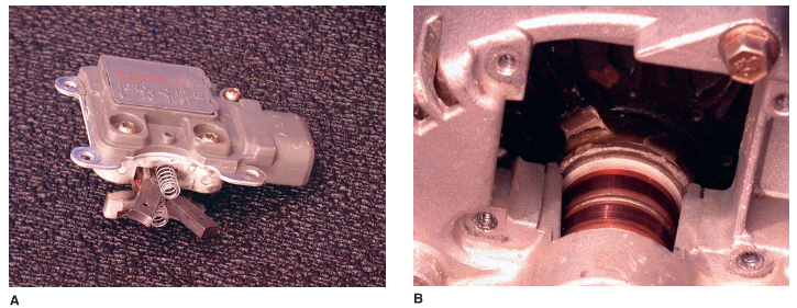
Figure 9.
A—These alternator brushes are mounted in the voltage regulator housing. The brush-regulator assembly bolts to the rear of the alternator housing.
B—With the brush-regulator assembly removed, you can see the slip rings on the rotor assembly. The brushes slide on the slip rings to make a rotating electrical connection with the rotor windings.
Small brush springs push the brushes out and into contact with the slip rings. Since current into the rotor windings is low, these brushes are small compared to motor brushes. See Figure 10.
A brush holder encloses the brush springs and brushes. It holds the brushes in alignment with the rotor slip rings. The brush holder is made of insulating material to prevent brush grounding.
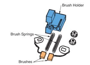
Figure 10. An insulating brush holder holds the springs and brushes in place over the slip rings. (Ford)
Rectifier Assembly
An automobile electrical system is designed to use direct current, which flows in only one direction. It cannot use the alternating current as it comes out of the alternator stator. Alternator current must be rectified (changed into direct current) before entering the electrical system.
This is accomplished by running the stator output through a series of diodes. Figure 11 shows how six diodes can be wired to produce full-wave rectification of the stator AC.
Figure 12 illustrates a typical method of wiring the diodes inside an alternator. Note how the stator leads are connected to the diode circuit. The output from the diodes is connected to the terminals on the outside of the alternator.
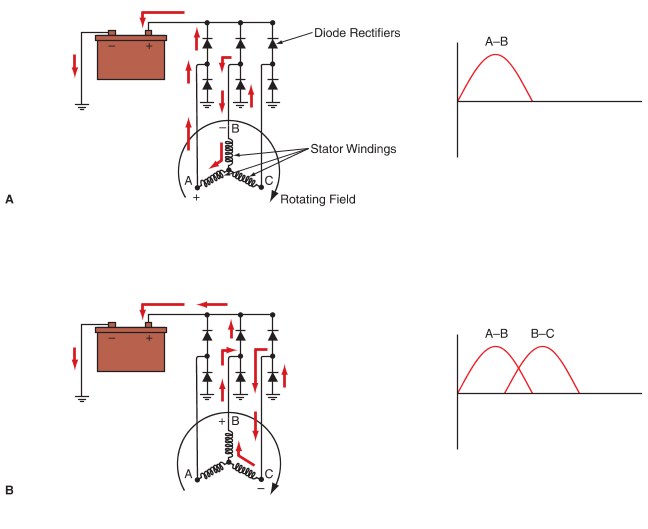
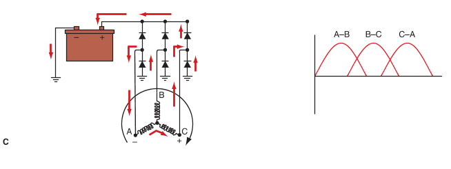
Figure 11. These diodes convert AC into DC. As the rotor turns, only two stator windings and two diodes are active at a time.
A—Winding A and B are active and form a series circuit. Current flows from winding A, through one diode, and to the positive post of the battery. It returns through one diode to winding B.
B—Current flows from winding B, through one diode, and to the positive post of the battery. It returns through one diode to winding C.
C—Current flows from winding C, through one diode, and to the positive post of the battery. It returns through one diode to winding A
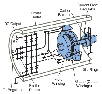
Figure 12. Typical wiring for the diodes, stator, rotor, and brushes in an alternator. (Bosch)
Fan and Pulley Assembly
To provide cooling for the alternator, a fan is mounted on the front of the rotor shaft. It is normally located between the pulley and the front bearing. As the rotor and shaft spin, the fan helps draw air through and over the alternator. This cools the windings to prevent damage from overheating.
The alternator belt runs from the crank pulley to the alternator pulley, which is secured to the front of the rotor shaft by a large nut. As the crankshaft turns, the alternator belt causes the alternator pulley to turn, which spins the rotor. One of three types of belts may be used: V-belt, cogged V-belt, or ribbed belt.
