Programmable logic controllers (PLCs) are useful in increasing production and improving overall plant efficiency. PLCs can control individual machines and link the machines together into a system.
The flexibility provided by a programmable logic controller has allowed its use in many applications for manufacturing and process control.
Process control has gone through many changes. In the past, process control was mostly accomplished through manual control. Flow, temperature, level, pressure, and other control functions were monitored and controlled at each stage by production workers.
Today, an entire process can be automatically monitored and controlled with few or no workers involved through the use of programmable logic controllers. Process applications in which PLCs are used include the following:
- grain operations that involve storage, handling, and bagging
- syrup refining that involves product storage tanks, pumping, filtration, clarification, evaporators, and all fluid distribution systems
- Fats and oils processing that involves product storage tanks, pumping, filtration, clarification, evaporators, and all fluid distribution systems
- dairy plant operations that involve all-process control from raw milk delivered to finished dairy products
- oil and gas production and refining from the well pumps in the fields to finished product delivered to the customer
- bakery applications from raw material to finished product
- beer and wine processing, including the required quality control and documentation procedures
PLC Timer Applications
An example of a controller timer application is a stop-light circuit. A stoplight circuit is a circuit that uses timers to the sequence when the red, yellow, and green lamps turn on and off. A stoplight timing circuit can use stand-alone timers or programmable timers to control the timing sequence.
The circuit is drawn as a standard line diagram when the stand-alone timer is used. Four on-delay timers are used for a basic stoplight timing sequence. See Figure 1. The stoplight circuit shows the basic operation of sequencing three lamps, and the time values have been reduced to seconds. Once the circuit start pushbutton is pressed and released, the lamps turn on and off in the following sequence:
- The red lamp turns on for 30 sec.
- The red lamp turns off and the yellow lamp turns on for 5 sec.
- The yellow lamp turns off and the green lamp turns on for 40 sec.
- The green lamp turns off and the yellow lamp turns on for 5 sec.
- The yellow lamp turns off and the red lamp turns on for 30 sec.
- Timer 4 resets the circuit and the sequence start over.
The circuit is drawn as a control line diagram when a programmable timer is used. The controller line diagram is similar to the standard line diagram, but the difference is that a standard line diagram is drawn by hand or by using a computer program.
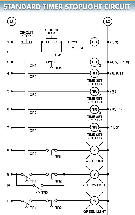
Figure 1. Four on-delay stand-alone timers are used for a basic stoplight timing sequence application.
The programmable timer line diagram is automatically drawn on the computer screen as the circuit is programmed. See Figure 2. In this diagram, each line of the control circuit is referred to as a rung.
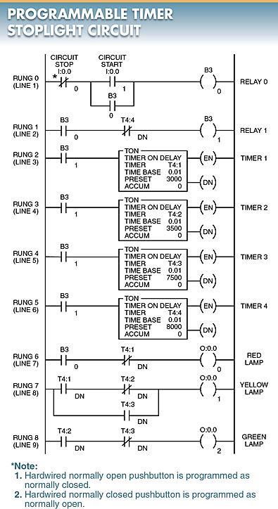
Figure 2. A programmable timer line diagram is automatically drawn on the computer screen as the circuit is programmed.
Starting with the number 0, each rung is identified by a number. Input, output, relay, and timer identification varies by manufacturer. The following is a common manufacturer identification method:
- The inputs are addressed as I: 0.0-0 (stop button) and I: 0.0-1 (start button).
- The outputs are addressed as 0:0.0-0 (red lamp), 0:0.0-1 (yellow lamp), and 0:0.0-2 (green lamp).
- The relays are addressed as B3-0 (first relay), and B3-1 (second relay).
- The timers are addressed as T4:1 (timer 1), T4:2 (timer 2), T4:3 (timer 3), and T4:4 (timer 4).
Input and Output Address Identification
Every time an I/O device on a programmable logic controller is programmed, the device must be assigned an address (instruction). The address links external inputs and outputs to data files and processor files within the controller.
Although each manufacturer assigns their own addresses to inputs and outputs, there are more similarities than differences among most manufacturers. For example, a typical manufacturer addressing numbering system uses number/letter assignments. See Figure 3.
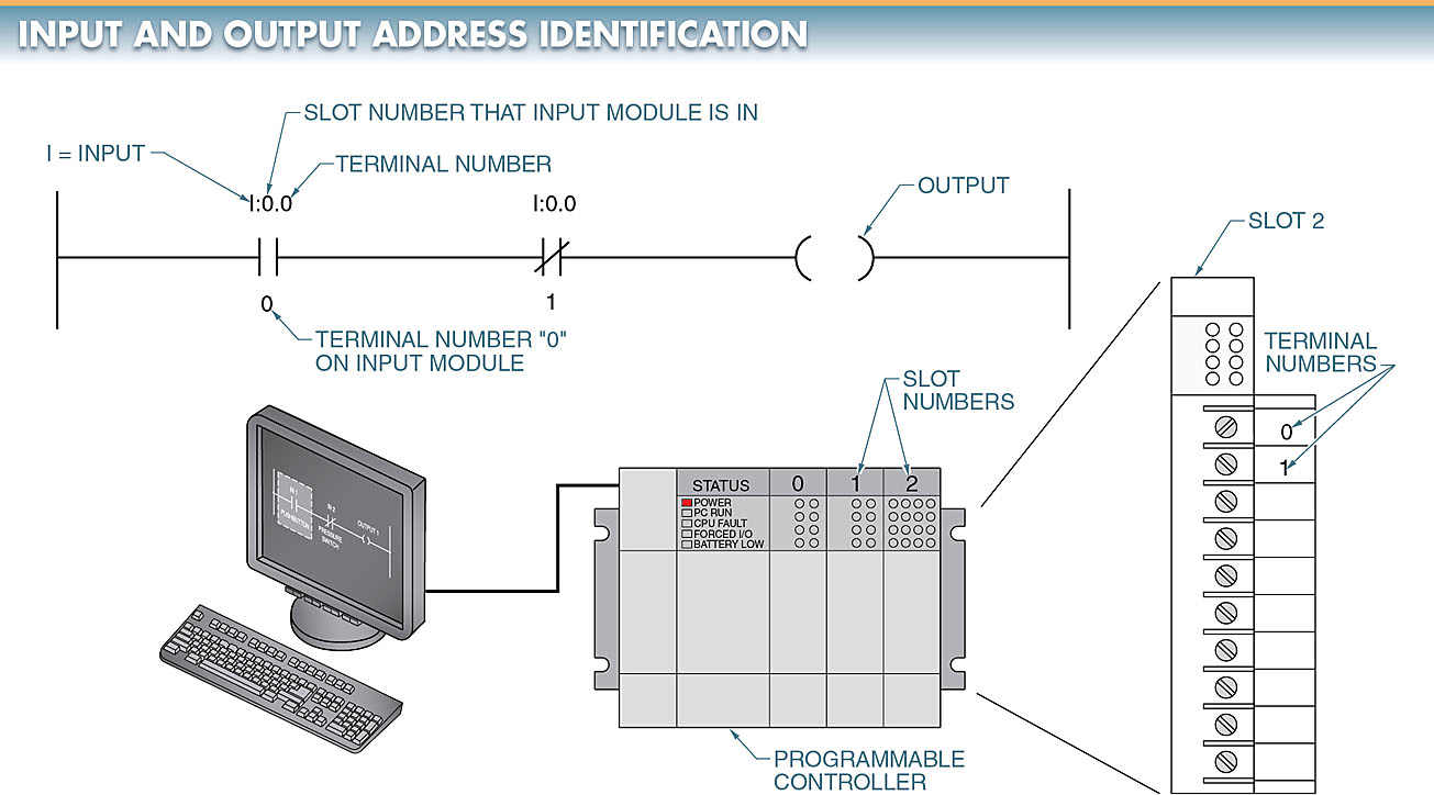
Figure 3. Numbers and letters are used to assign addresses to inputs, outputs, timers, and other internal and external components.
The numbering/letter assignments are made as follows:
I = Input (pushbutton, limit switch, etc.)
O = Output (solenoid, lamp, motor starter, etc.)
T = Timer (internal PLC timer)
C = Counter
: = Slot number (physical slot number [1, 2, 3, etc.] of the I/O module)
For example, I:0/1 identifies an input in slot number 0 at terminal 1 and 0:0/4 identifies an output in slot number 0 at terminal 4.
Welding
In discrete parts manufacturing, welding is often a major part of the system. Programmable logic controllers may be used to control and automate industrial welding processes. See Figure 4.
In this application, the programmable logic controller can control the length of the weld and the power required to produce the correct weld. The controller is programmed to allow the weld to occur only if all inputs and conditions are correct. These inputs and conditions include the following:
- presence and correct position of all the parts
- the correct weld cycle speed and power setting
- the correct rate of speed on the line for the given application
- proper functioning of all interlocks and safety features
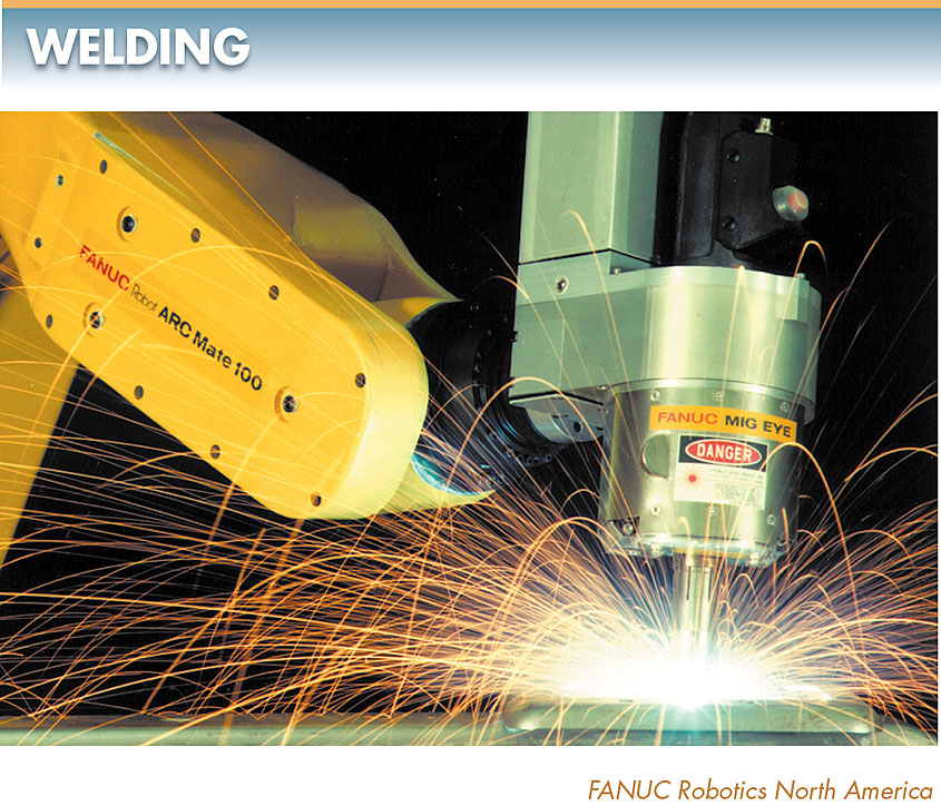
Figure 4. Programmable logic controllers can be used to control and automate industrial welding processes.
In addition, the controller can be used to determine whether parts are running low and can be set to automatically turn the line on and off as required.
Documentation of production efficiency can be generated for quality control and inventory requirements. A programmable controller may be used to control and interlock many welders.
Welders at one station may require more power than is available in all the welders are ON simultaneously. In this case, a large power draw can cause poor-quality welds. A requirement for a system using many welders is to limit the amount of power being consumed at any one time. This is accomplished by time-sharing the power feed to each welder. A programmable logic controller may be programmed for a maximum power draw. The controller can determine whether power is available when a welder requires power.
The weld takes place if the correct power level is available. If not, the controller remembers the request and permits the welder to proceed with the weld cycle when power is available. The controller can also be programmed to determine which welder has priority.
Machine Control
Controls must be synchronized when machines are linked together to form an automated system. See Figure 5.
In this application, each machine may be controlled by a PLC, with another PLC synchronizing the operation. This situation is likely if the machines have been purchased from different manufacturers. In this case, each machine may include a controller to control all the functions on that machine only. If the machines are purchased from one manufacturer or designed in-plant, it is possible to use one large controller to control each machine and synchronize the process.

Figure 5. Controllers are used to controlling and synchronizing individual machine operations with other machines.
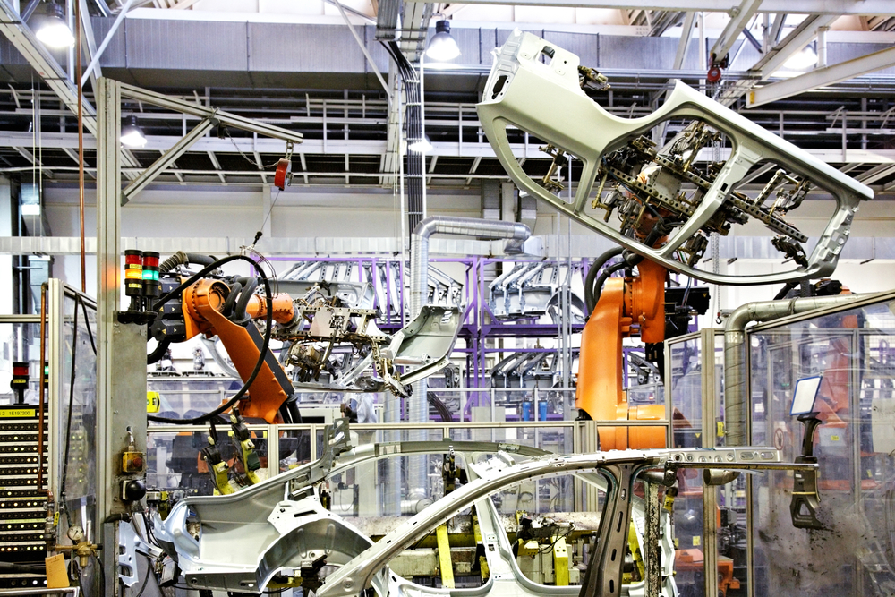
Industrial Robot Control
Programmable logic controllers are ideal devices for controlling an industrial robot. See Figure 6. A PLC can be used to control all operations such as rotate, grip, withdraw, extend, and lift. A controller is recommended because most robots operate in an industrial environment.
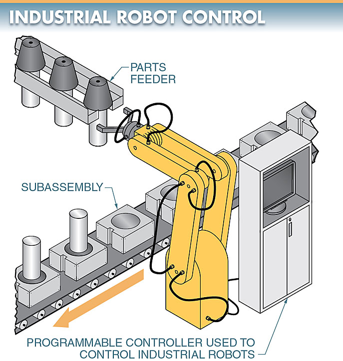
Figure 6. Controllers can be used to control the operations of an industrial robot.
Fluid Power Control
Fluid power cylinders are normally chosen when a linear movement is required in an automated application.
Pneumatic cylinders are common because they are easy to install and most plants have access to compressed air. Pneumatics work well for most robot grippers, drives, and positioning cylinders, as well as machine loading and unloading and tool-working applications.
Hydraulic cylinders are used when a manufacturing process requires high forces. Hydraulic systems of several thousand psi are often used to punch, bend, form, and move components.
PLCs may be used to control linear and rotary actuators in an industrial fluid power circuit. See Figure 7. In this system, the output module of the programmable logic controller is connected to control the four solenoids. Solenoid A moves the cylinder in, solenoid B moves the cylinder out, solenoid C rotates the rotary actuator in the forward direction, and solenoid D rotates the rotary actuator in the reverse direction.
The controller is used to control the energizing or de-energizing of the solenoids. Solenoids control the directional control valves, which control the actuators.
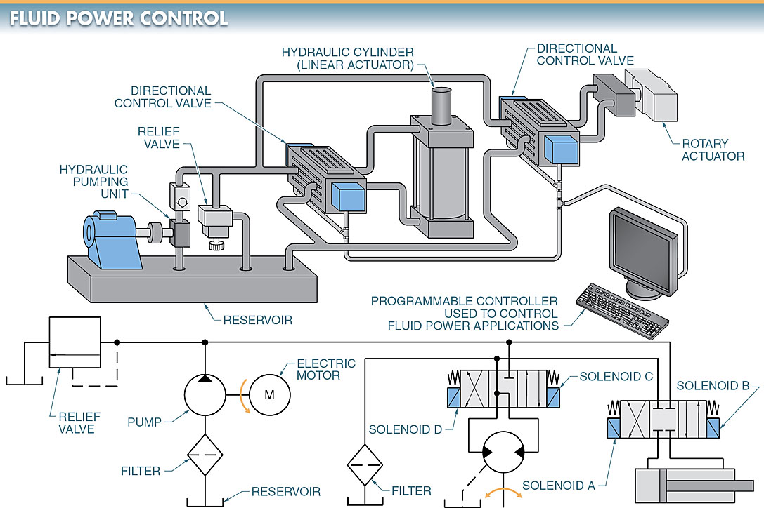
Figure 7. Controllers can be used to control linear and rotary actuators in an industrial fluid power circuit.
Industrial Drive Control
Motors are often directly connected to the power lines and operate at a set speed. As systems become more automated, variable motor speed is required. Adjustable speed controllers are available to control the speed of AC and DC motors. These controllers are normally manually set for the desired speed, but many allow for automatic control of the set speed. A PLC may be used to control AC drives. See Figure 8.
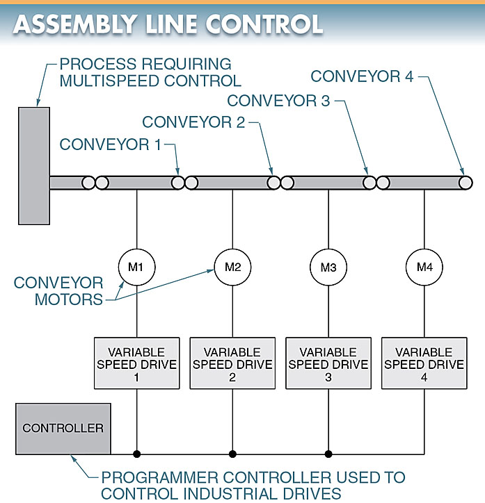
Figure 8. Controllers can be used to control and synchronize the speed of conveyors on an assembly line.
The drives can accept frequency and direction commands in a BCD format that the PLC can provide with a BCD output module.
Pulp and Paper Industries
Pulp and paper industries use programmable logic controllers to control each production process and diagnose problems in the system. See Figure 9.
Pulp and paper production processes can involve equipment that covers a large area. The control of pulp and paper production processes is ideal for a PLC because most control logic includes start/stop, time delay, count sequential, and interlock functions.
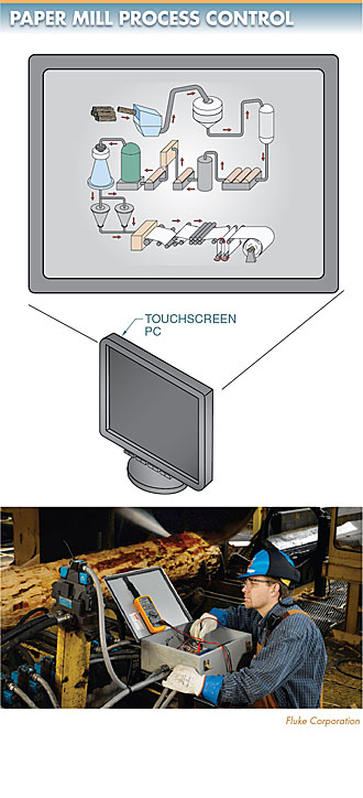
Figure 9. Controllers in a paper mill control each process and diagnose problems in the system.
A PLC allows for the required inputs and outputs, which, when multiplexed, can transmit multiple signals over a single pair of wires.
The basic operation of a paper mill is to receive raw material such as logs, pulpwood, or chips and then process, size, store, and deliver the material. This operation includes a large conveyor system with diverter gates, overtravel switches, speed control, and interlocking.
A break in any part of the system can shut down the entire system. Attempts to find a fault can be time-consuming since the system covers a large area. To solve this problem, a programmable logic controller with fault diagnostics can be used to analyze the system and give an alarm and printout of where the problem exists with suggested solutions.
Batch Process Control Systems
Batch processing blends sequential, step-by-step functions with continuous closed-loop control. Because systems are made up of many parts, batch process control is essentially system control. Individual PLCs can be used to control each part and step of the process, with additional controllers and computers supervising the total operation.
In a batch process control system, an operator interface is used for instrumentation or other monitoring functions. An operator interface is added as part of the system. This interface may be in the form of an instrumentation and process control station, an HMI, or any other type of interface.
To aid in interfacing and monitoring a programmable-based system, a serial port is used for monitoring and programming a system using a computer. Thus, the individual solenoids, motor starters, and heating elements at each process step are directly controlled by the local programmable logic controllers while the host computer L1 supervises all of the controllers. See Figure 10.
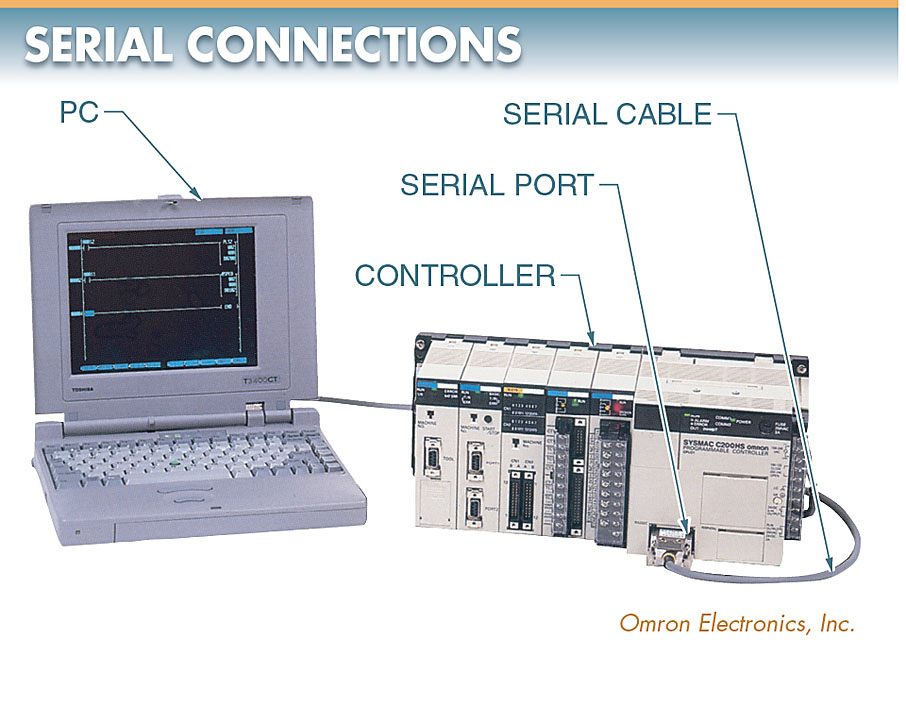
Figure 10. A serial port is used for monitoring and programming a system using a computer.
