Control devices such as push buttons, limit switches, and pressure switches are connected into a circuit so that the circuit can function in a predetermined manner. All control circuits are basic logic functions or combinations of logic functions.
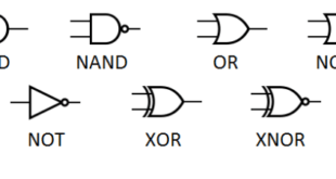
Logic functions are common to all areas of industry. This includes electricity, electronics, hydraulics, pneumatics, math, and other routine activities. Logic functions include AND, OR, AND/OR, NOT, NOR, and NAND.
Common logic functions have been used to develop circuit logic since the first electrical circuits were used. Line (ladder) diagrams are one of the oldest and most common methods of illustrating and understanding basic logic functions.
Programmable logic controller (PLC) programming diagrams decrease the design time needed for electrical circuits and add flexibility by reprogramming electrical circuits using software instead of rewiring.
The basic logic functions of a circuit remain the same; however, the PLC programming diagram is drawn in a generic manner to allow for greater flexibility when the circuits are reprogrammed.
Programmable logic relay (PLR) function block diagrams are another method of designing and drawing circuit logic using simple logic blocks. A PLR function block diagram is a simplified way of showing common circuit logic functions by connecting inputs and outputs to a logic block labeled with the desired logic function.
PLCs and PLRs can be programmed using standard line (ladder) programming or function block diagrams. Some PLCs and PLRs allow the user to select either method. Once the basic circuit design methods are understood, any method can be used to program a circuit. On each type of diagram, each of the basic logic functions is shown using each format. The function of the electrical circuit is exactly the same for each type of diagram.
AND Logic
AND logic is used in industry when two NO push buttons are connected in series to control a solenoid. See Figure 1. PB1 and PB2 must be pressed before the solenoid is energized. The logic function that makes up the decision section of this circuit is AND logic. The reason for using the AND function could be to build in safety for the operator of this circuit.

Figure 1. In AND logic, the load is ON if both of the control signal contacts are closed.
If the solenoid were operating a punch press or shear, the pushbuttons could be spaced far enough apart so that the operator would have to use both hands to make the machine operate. This ensures that the operator’s hands are not near the machine when it is activated.
With AND logic, the load is ON only if all the control signal contacts are closed. As with any logic function, the signals may be manually, mechanically, or automatically controlled.
Any control device such as limit switches, pressure switches, etc., with NO contacts can be used in developing AND logic. The NO contacts of each control device must be connected in series for AND logic.
A simple example of AND logic takes place whenever an automobile that has an automatic transmission is started. The ignition switch must be turned to the start position and the transmission selector must be in the park position before the starter is energized.
Before the action (load ON) in the automobile circuit can take place, the control signals (manual) must be performed in a logical manner (decision).
OR Logic
OR logic is used in industry when an NO push button and an NO temperature switch are connected in parallel. See Figure 2. In this circuit, the load is a heating element that is controlled by two control devices.
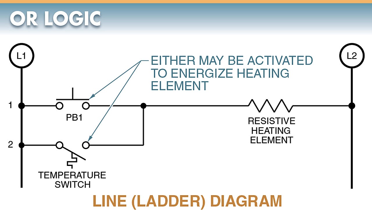
Figure 2. In OR logic, the load is ON if any one of the control signal contacts is closed.
The logic of this circuit is OR logic because either the pushbutton or the temperature switch energizes the load.
The temperature switch is an example of an automatic control device that turns the heating element on and off to maintain the temperature setting for which the temperature switch is set.
The manually controlled pushbutton could be used to test or turn on the heating element when the temperature switch contacts are open.
In OR logic, the load is ON if any one of the contacts of the control signal is closed. The control devices are connected in parallel.
Series and parallel refer to the physical relationship of each control device to other control devices or components in the circuit. This series and parallel relationship is only part of what determines the logic function of any circuit.
An example of OR logic is in a dwelling that has two pushbuttons controlling one bell. The bell (load) may be energized by pressing (signal ON) either the front or the back pushbutton (control device). In this example, as in the automobile circuit example, the control devices are connected to respond in a logical manner.
AND/OR Logic Combination
The decision section of any circuit may contain one or more logic functions. See Figure 3. In this circuit, both pressure and flow must be present in addition to the pushbutton or the foot switch being engaged to energize the starter coil (load). This provides the circuit with the advantage of both AND logic and OR logic.
The machine is protected because both pressure and flow must exist before it is started, and there is a choice between using a push button or a foot switch for final operation. The action taking place in this circuit is energizing a coil in a magnetic motor starter. The signal inputs for this circuit have to be two automatic and at least one manual.

Figure 3. The decision section of any circuit may contain one or more logic functions.
Each control device responds to its own input signal and has its own decision-making capability.
When multiple control devices are used in combination with other control devices making their own decisions, a more complex decision can be made through the combination of all control devices used in the circuit.
All industrial control circuits consist of control devices capable of making decisions in accordance with the input signals received.
NOT Logic
NOT logic has an output if the control signal is OFF. For example, replacing NO contacts on a pushbutton with NC contacts energizes the solenoid and pilot light without pressing the pushbutton. See Figure 4.
In this circuit, the loads are de-energized when the push button is pressed. There must not be a signal if the loads are to remain energized. With NOT logic, the output remains on only if the control signal contacts remain closed.
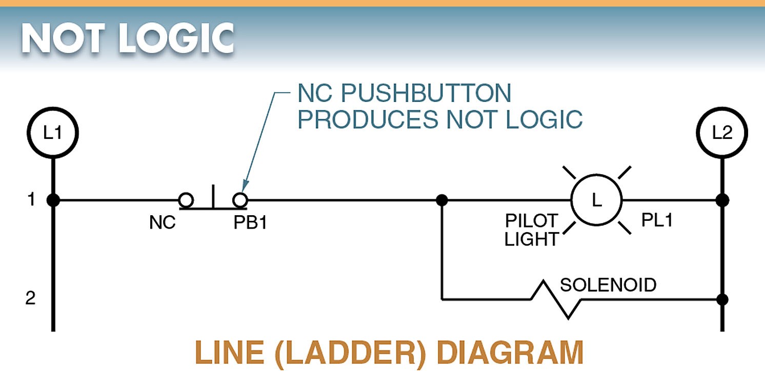
Figure 4. In NOT logic, the load is ON only if the control signal contacts are closed.
An example of NOT logic is the courtesy light in a refrigerator. The light is ON if the control signal is OFF. The control signal is the door of the refrigerator. Any time the door is open (signal OFF), the load (courtesy light) is ON. The condition that controls the signal can be manual, mechanical, or automatic. With the refrigerator door, the condition is mechanical.
NOR Logic
NOR logic is an extension of NOT logic in which two or more NC contacts in series are used to control a load. See Figure 5.
In this circuit, additional operator safety is provided by adding several emergency stop pushbuttons (NOT logic) to the control circuit. The load (coil M1) is de-energized by pressing any emergency stop pushbutton.
By incorporating NOR logic, each machine may be controlled by one operator, but any operator or supervisor can have the capability of turning off all the machines on the assembly line to protect individual operators or the entire system.
With the knowledge of NOR logic, the electrician can readily add stop push buttons by wiring them in series to perform their necessary function.
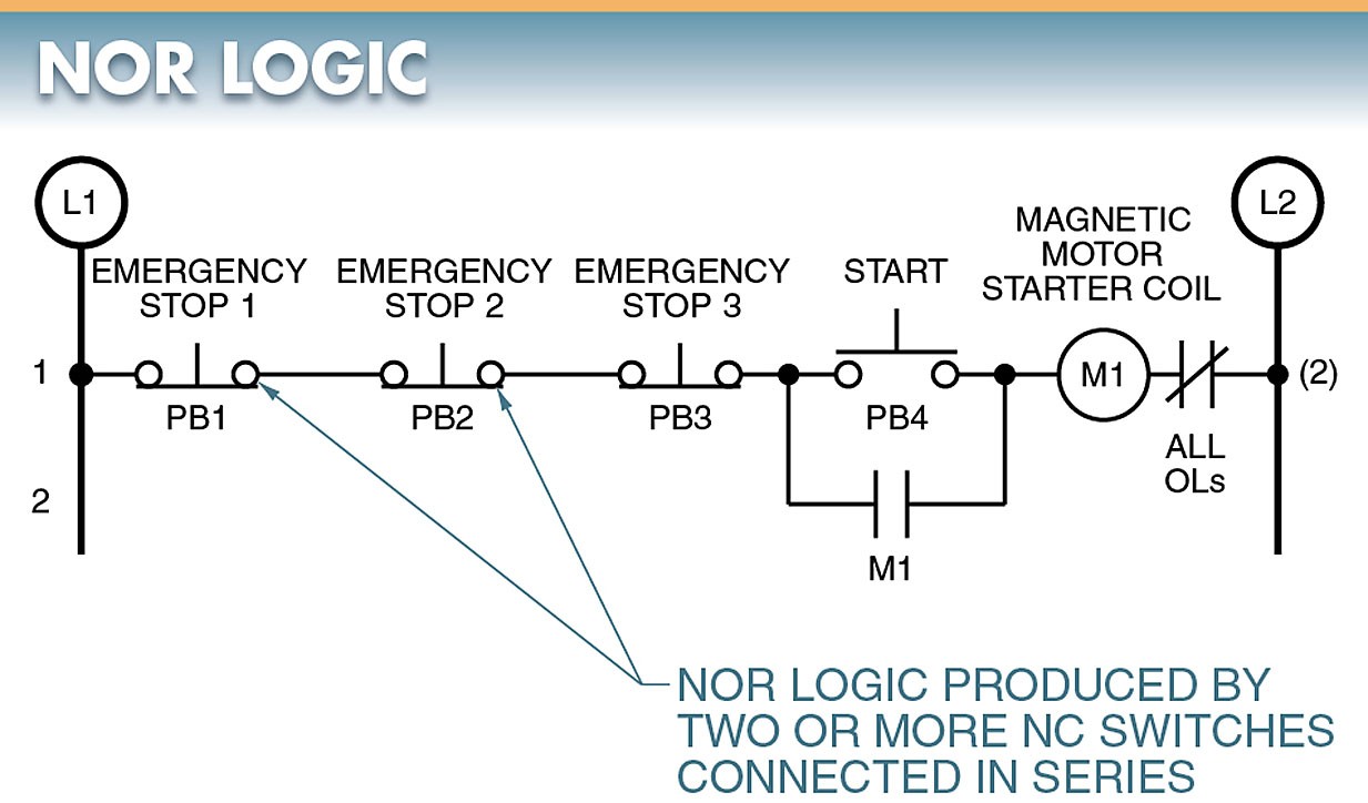
Figure 5. NOR logic is an extension of NOT logic in which two or more NC contacts in series are used to control a load.
NAND Logic
NAND logic is an extension of NOT logic in which two or more NC contacts are connected in parallel to control a load. See Figure 6.
In the circuit depicted, two interconnected tanks are filled with a liquid. When pushbutton PB3 is pressed, coil M1 is energized and auxiliary contacts M1 close until both tanks are filled. Both tanks fill to a predetermined level because the float switches in tank 1 and tank 2 do not open until both tanks are full.
Every NOT logic must be open (signal OFF) to stop the filling process based on the input of the float switches. NOR logic is also present in this circuit because the emergency stops (NOT) at tank 1 or tank 2 may be used to stop the process if an operator at either of the tanks sees a problem.
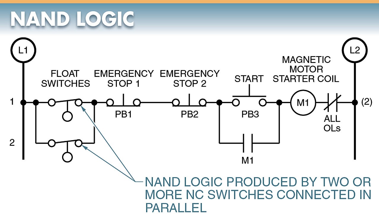
Figure 6. NAND logic is an extension of NOT logic in which two or more NC contacts are connected in parallel to control a load.
An example of a NAND circuit is the courtesy light in an automobile. In an automobile, the courtesy lights are ON if the control signal (door switches) is OFF (normally closed). This circuit is different from a refrigerator door in that an automobile may have two or more door switches, any of which will turn on the courtesy lights.
