The vacuum tube is a direct result of Thomas Edison’s experiment with the incandescent lamp. In this experiment, a metal plate was placed in the vacuum bulb containing the filament. A battery and series meter were connected between the light filament and the plate.
At this point, Edison discovered that electric current would flow through the light if the positive terminal of the battery was connected to the plate. However, if the negative battery terminal was connected to the plate, no current would flow. See Figure 1.
At that time, the electron theory had not yet been discovered, and the flow of current through the light was a mystery.
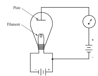
Figure 1. Circuit diagram of the Edison discovery.
Today, we understand electron theory. Certain metals and metal oxides give up free electrons when heated. The heat supplies enough energy to the electrons to cause them to break away from the forces holding them in orbit. They become free electrons. This process is known as thermionic emission.
In Edison’s experiment, a cloud of free electrons was emitted from the filament of the light bulb. When a positive plate was placed in the bulb, the free electrons were attracted to the plate. (Unlike charges attract.) A flow of electrons means that a current is present.
The meter attached to the plate circuit showed that electrons were passing from filament to plate. The vacuum tube uses the same principles discovered in the laboratory of Thomas Edison.
Thermionic Emitters
Better emitting materials have been developed in the years since Edison’s carbon filament. Many materials, when heated to the point of emission, will melt.
For many years, tungsten seemed to be the best material. It required a great deal of heat for proper emission, yet it was strong and durable. Tungsten is still used in large, high-power vacuum tubes.
To lower the working temperatures and power usage, the thoriated-tungsten emitter was developed. It consisted of a thin layer of thorium placed on the tungsten emitter.
Thorium is one of the heaviest metallic elements. Its symbol is Th, and its atomic weight is 232.04. This type of emitter produces the proper emission at much lower temperatures than pure tungsten.
The most efficient emitter is the oxide-coated type. The emitter is a metal, such as nickel. On the emitter, a thin layer of barium or strontium oxide is formed. Because of its low power usage and high emission, this type of emitter was widely used in vacuum tubes for radios, televisions, and other electronic devices.
Thermionic Vacuum Tubes
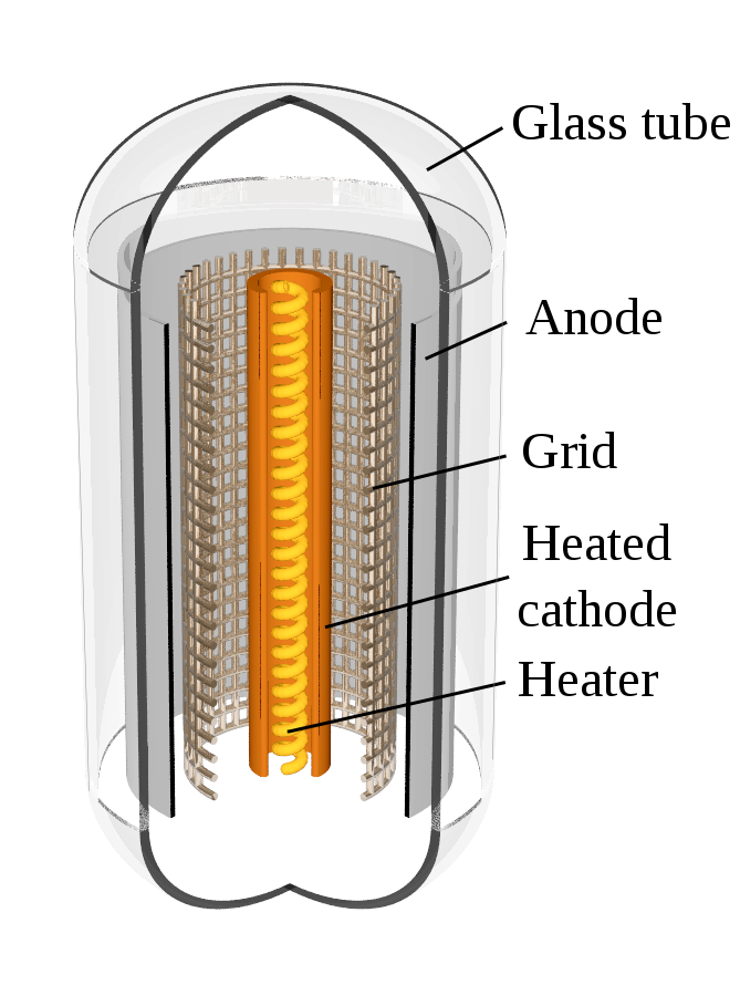
Cathodes
The emitter in the vacuum tube is called the cathode. Heat can be supplied either directly or indirectly. Both methods have certain advantages. Schematic diagrams of both types of tube are shown in Figure 2.
Equipment that uses batteries for power works best with directly heated cathodes. There is less heat loss, and the filament can be designed so that only a small amount of power is consumed during use.
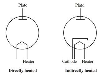
Figure 2. Schematic symbols of directly and indirectly heated cathodes.
When an AC source is handy, the indirectly heated cathode is more useful. There is little power loss, and the heater voltage source and cathode can be separated. This eliminates any humming in the circuit.
Diodes
A diode consists of two electrodes. In the case of a vacuum tube diode, the two electrodes are the cathode and plate. Again, the cathode can be heated directly or indirectly. The plate is a round piece of metal that surrounds all elements in the tube. The plate acts as the collector of electrons emitted from the cathode. See Figure 3. The heater connections are H1 and H2. These connections can be joined to an AC source.
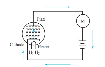
Figure 3. Diode circuit shows direction of electron flow.
The first number in a tube name is the approximate voltage that should be applied to the heaters. For example, a 6H6 tube needs 6.3 volts; a 12AX7 needs 12.6 volts; a 25Z6 needs 25 volts.
When the tube in Figure 3 is turned on, the heaters indirectly heat the cathode. This causes thermionic emission of electrons. If the diode plate is joined to the positive terminal of the battery in the circuit, electrons will flow in the circuit from cathode to plate. If the connections are reversed, no electrons will flow. This electron tube acts as a one-way valve. It permits electron flow in one direction only.
At a certain temperature, the cathode emits the largest number of electrons. These electrons form a charge around the cathode. The cathode has been made slightly positive because of the emission of electrons. Some of these electrons are attracted back to the cathode.
When the plate is made positive, many electrons are attracted to it. This is electron flow. The plate can be made more positive by applying a higher voltage. A greater number of electrons are attracted, and there is an increase in current.

Diode: electrons from the hot cathode flow towards the positive anode, but not vice versa
Figure 4 shows the increase in current as a result of an increase in plate voltage. At some point, as voltage is increased, all the emitted electrons will be attracted to the plate. Any further increase in voltage will not increase the current. This is called the saturation point of the electron tube.
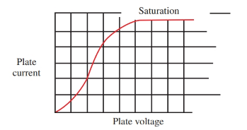
Figure 4. As plate voltage increases, plate current increases until the point of saturation.
Triodes
A triode is a three-element tube made of a cathode, plate, and grid. The triode was developed by Dr. Lee DeForest. In his experiments, DeForest inserted a fine wire mesh between the cathode and the plate of the tube. In doing this, he was able to control electron flow through the tube. This wire mesh is the grid.
The grid in the triode most often has a cylindrical shape and it surrounds the cathode. The space between the grid wires allows electrons room to pass through to the plate. The grid controls electron flow and is commonly called the control grid.
Electron flow is controlled by changes in plate voltage. In the triode, the grid also affects electron flow. For example, a negative grid will repel many electrons back to the cathode. This limits the number of electrons passing on to the plate.
As the grid is made more and more negative, a point is reached where no electrons flow to the plate. This is the cutoff point of the tube. It is the negative voltage amount applied to the control grid that stops electron flow. The voltage applied to the control grid is called the bias voltage. At cutoff, it is called the cutoff bias.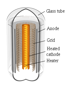
Triode: voltage applied to the grid controls plate (anode) current.
A triode with both plate and grid voltage is shown in Figure 5. Notice that the grid bias battery has its negative terminal connected to the grid. In electronic work, these voltages have specific names such as A, B, and C.
The A voltage is for the heaters in the tube. The B voltage is for the plate of the tube. The C voltage is for the grid of the tube.
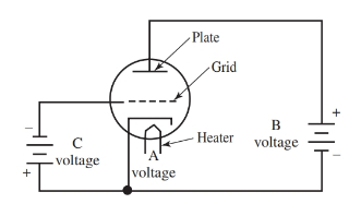
Figure 5. This triode circuit shows the connections for plate voltage and grid bias voltage.
Figure 6 shows current through an electron tube as the grid bias is changed. The plate voltage is held at a constant value. The curve in this graph is plotted by measuring the value of current at each change of grid voltage. At a grid bias of negative two volts, the current is eight mA. At negative six volts, the current drops to three mA.
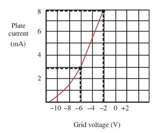
Figure 6. The change in plate current as a result of change in grid voltage. The plate voltage is held at a constant value.
Tetrodes
Without neutralization circuits, the triode is limited as an amplifier due to the shunting effect of electrode capacitance at high frequencies, Figure 7. To overcome this drawback, another grid is inserted in the triode. This grid is called the screen grid. It is placed between the control grid and the plate. The resulting four-element tube (cathode, control grid, screen grid, and plate) is called a tetrode, Figure 8.
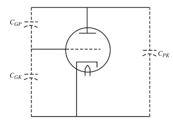
Figure 7. Dotted lines show capacitance between the elements in a tube.
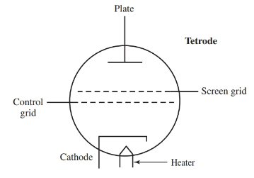
Figure 8. Symbol for a tetrode.
The screen grid is bypassed to ground, externally, through a capacitor. The grid is a good screen between the control grid and plate, and it stops the grid-plate capacitance (CGP).
A DC voltage, slightly less in value than the plate voltage, is applied to the screen grid. The screen grid increases the speed of the electrons passing between cathode and plate. Some electrons are attached to the screen grid causing a current to flow in the screen circuit. However, most electrons pass through the screen to the plate.
High amplification is possible in the tetrode because the control grid is placed very close to the cathode. A decrease or increase in plate voltage has little effect on the plate current due to the isolation effect of the screen grid.
Pentodes
While a tetrode has four elements, a pentode has five elements. In the tetrode, the electrons speed up to strike the plate with force. When this occurs, loosely held electrons on the plate are knocked off into free space. They form a space charge around the plate. This is called secondary emission.
Some of these electrons are drawn to the screen. They detract from useful plate current through the tube. This effect is more pronounced when plate voltage is below screen voltage.
To overcome the drawbacks of secondary emission, a third grid is placed in the tube between the screen grid and plate. This grid is called the suppressor grid. The tube now has five elements (cathode, control grid, screen grid, suppressor grid, and plate). This tube is called a pentode, Figure 9.
The suppressor grid is connected internally to the cathode at the cathode potential. This grid repels free electrons resulting from secondary emission and drives them back to the plate.
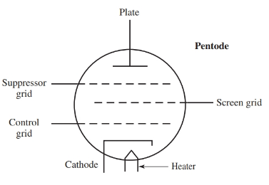
Figure 9. Symbol for a pentode.
These tubes have high amplification factors and high plate resistance. Interelectrode capacitance is at a mini- mum. Pentodes were once used as radio frequency (rf) amplifiers and as audio power amplifiers.
