This article covers the SCR Working Principle (Operation), Characteristics Curves, Phase Control, Triggering Methods, and Testing using DMM along with circuit diagrams.
A silicon-controlled rectifier (SCR) is a four-layer (PNPN) semiconductor device that uses three electrodes for normal operation. See Figure 1. The three electrodes are the anode, cathode, and gate.
The anode and cathode of an SCR are similar to the anode and cathode of an ordinary diode. The gate serves as the control point for an SCR. SCRs are also known as thyristors.
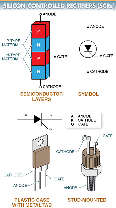
Figure 1. A silicon-controlled rectifier (SCR) has three electrodes called the anode, cathode, and gate.
SCR Working Principle
An SCR differs from an ordinary diode in that it does not pass significant current, even when forward biased unless the anode voltage equals or exceeds the forward break-over voltage.
However, when the forward break-over voltage is reached, the SCR switches on and becomes highly conductive. The gate current is used to reduce the level of break-over voltage necessary for the SCR to conduct or fire.
Low-current SCRs can operate with an anode current of less than 1 A. High-current SCRs can handle load currents in the hundreds of amperes. The size of an SCR increases with an increase in the current rating. See Figure 2.
SCRs have voltage ratings of up to 2500 V and current ratings of up to 3000 A. SCRs are used in power switching, phase control, battery charger, and inverter circuits.
In industrial applications, they are applied to produce variable DC voltages for motors (from a few to several thousand horsepowers) from AC line voltage. They can also be used in some electric vehicles.
SCRs may be used alone in a circuit to provide one-way current control or wired in reverse-parallel circuits to control AC line current in both directions. See Figure 3.
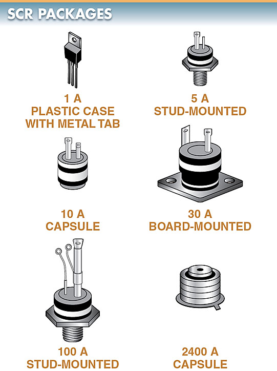
Figure 2. SCRs come in a variety of packages, which increase with an increase in current rating.
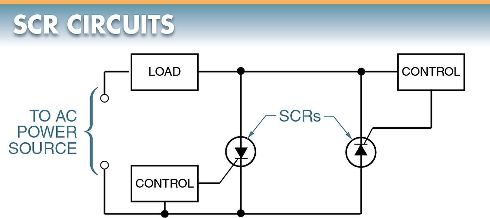
Figure 3. SCRs may be used alone in a circuit to provide one-way current control or wired in reverse-parallel circuits to control AC line current in both directions.
SCR Characteristic Curves
A voltage-current characteristic curve shows the operating characteristics of an SCR when its gate is not connected. See Figure 4. When an SCR is reverse biased, it operates similarly to a regular semiconductor diode.
When an SCR is forward biased, there is a small amount of forward leakage current called forward blocking current. This current stay relatively constant until the forward break-over voltage is reached. At that point, the current increases rapidly. The region is often called the forward avalanche region.
In the forward avalanche region, the resistance of the SCR is very small. The SCR operates similar to a closed switch, and the current is limited only by the external load resistance.
An SCR is either ON or OFF. When an applied voltage is above the forward break-over voltage (VBRF), the SCR fires or turns on.
The SCR remains on as long as the current stays above the holding current. When the voltage across the SCR drops to a value too low to maintain the holding current, it returns to its OFF state.
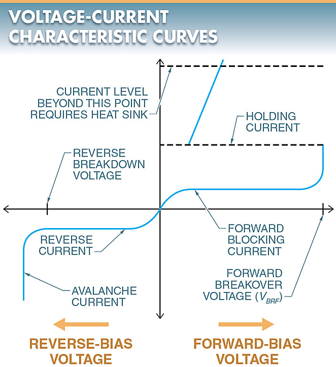
Figure 4. The voltage-current characteristic curve of an SCR shows how the SCR operates.
Gate Control of Forward Break-Over Voltage
When the gate is forward biased and current begins to flow in the gate-cathode junction, the value of forward break-over voltage can be reduced.
Increasing values of forward bias can be used to reduce the amount of forward break over voltage necessary to get the SCR to conduct.
Once the SCR has been turned on by the gate current, the gate current loses control of the SCR forward current. Even if the gate current is completely removed, the SCR remains on until the anode voltage has been removed.
The SCR also remains on until the anode voltage has been significantly reduced to a level where the current is not large enough to maintain the proper level of holding current.
SCR Triggering Methods
An SCR normally can be triggered into conduction by applying a pulse of the control current to the gate. Once turned on, an SCR remains on as long as there is a minimum level of holding current flowing through the load circuit.
Once the current drops below the holding current value, the SCR turns off. See Figure 5. The correct method of turning on an SCR is to apply a proper signal to the gate of the SCR (gate turn-on).
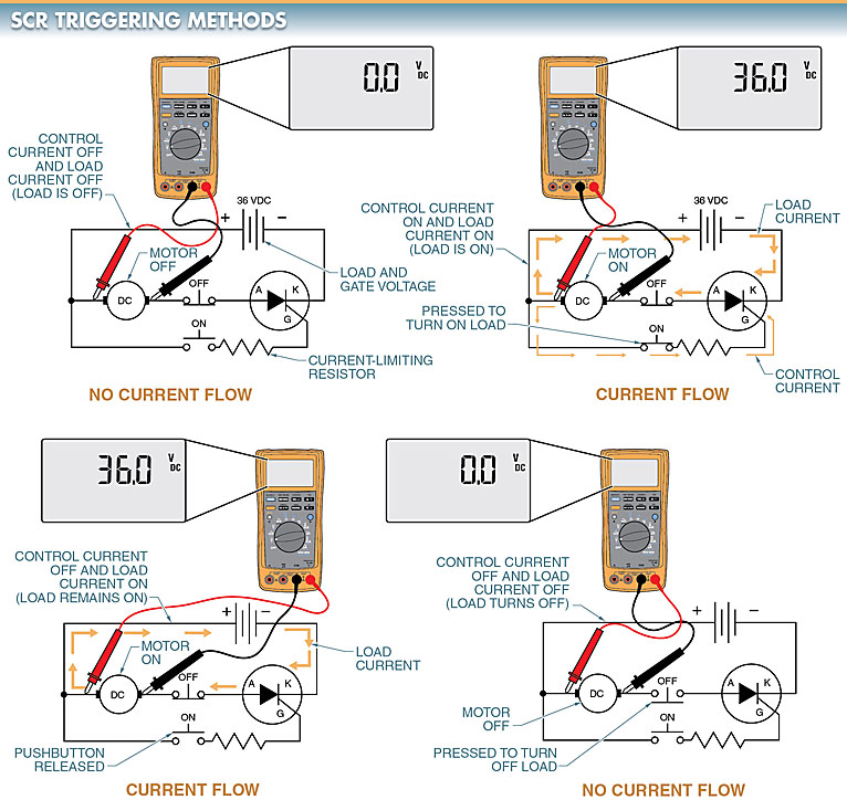
Figure 5. An SCR is turned on by applying a pulse of the control current to the gate. Once turned on, an SCR remains on as long as there is a minimum level of holding current flowing through the load circuit.
SCR Phase Control
The ability of an SCR to turn on at different points in the conducting cycle can be used for varying the amount of power delivered to a load. This type of variable control is called phase control.
Phase control is the control of the time relationship between two events when dealing with voltage and current. In this case, it is the time relationship between the trigger pulse and the point in the conducting cycle when the pulse occurs.
With phase control, the speed of a motor, the brightness of a lamp, and the output of an electric-resistance heating unit can be controlled.
The most basic control circuit using this principle is a half-wave phase control circuit.
A half-wave phase control circuit is an SCR that has the ability to turn on at different points of the conducting cycle of a half-wave rectifier. See Figure 6. In this circuit, the input voltage is a standard 60 Hz line voltage.
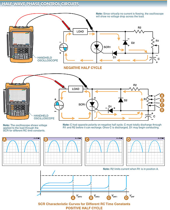
Figure 6. On the negative half cycle, SCR1 is reverse biased and does not conduct. On the positive half cycle of the AC input, the SCR is forward biased such that gate current will flow through diode D1 and variable resistor R1, causing the SCR to conduct.
When a negative half cycle is applied to the circuit, the SCR is reverse biased and should not conduct.
In addition, diode D1 is reverse biased and no gate current flows. Diode D2, however, is forward biased and allows capacitor C to charge to the polarity shown. No current flows through R1 since D2 is in parallel with R1.
The forward-biased resistance of D2 is so much lower than R1 that almost all current passes through D2 instead of through R1. Since no current is flowing through the load, the oscilloscope should not indicate a voltage drop.
Note: The oscilloscope on the negative half cycle should show only a slight movement of the trace. This is because the SCR is reverse biased and the current drawn through diode D2 when charging capacitor C, is small.
When the positive half cycle of the voltage source is applied, the circuit operation changes. When the positive half cycle is applied to the circuit, the SCR becomes forward biased in such a way that it conducts forward current if a gate current of sufficient strength is present.
The important factor is the amount of gate current. If the gate current is too small, the SCR does not fire. The amount of gate current in this circuit is controlled by variable resistor R1 and capacitor C.
Resistor R1 and capacitor C form an RC network that determines the time of charge and discharge of the capacitor.
For capacitor C to charge on the positive half cycle, it must first discharge the polarities it received on the negative half cycle. Once discharged, it may recharge with the opposite polarity.
The charging and discharging rates are determined by resistor R1. The discharge and charge time of the RC network determine the time sufficient current is allowed to flow through the gate circuit to fire the SCR.
If variable resistor R1 is in position A or has no resistance, the capacitor will discharge its reverse polarity almost immediately. Current would then be allowed to pass through D1, which in turn fires the SCR. The result is that the entire positive half cycle is allowed to pass through the SCR to the load as shown by the oscilloscope display pattern correlated to position A.
If variable resistor R1 is moved to position B, where more resistance is placed in the RC network, the time of discharge for C is increased. The result is a delay in time for the gate current to reach its necessary value. Also, part of the positive half cycle is blocked as shown by the oscilloscope display pattern correlated to position B.
As more resistance is added to positions C and D, the time delay is increased. The result is that the positive half cycle is increasingly blocked while a decreasing amount of current is delivered to the load. Thus, the SCR can then deliver a varied output to the load on the positive half cycle.
Note: To control the output in both the positive and negative half-cycles, two SCRs must be used.
Controlling DC Motor Base Speed with SCRs
DC motor control is one of the most suitable industrial applications of SCRs.
In DC motor control applications, an SCR can be used to control the speed of a DC motor below the base speed by changing the amount of current that flows through the armature circuit. Speed below the base speed is controlled by changing the armature voltage.
Base speed is the speed (in rpm) at which a DC motor runs with a full-line voltage applied to the armature and field.
The speed of a DC motor is controlled by varying the applied voltage across the armature and/or field. When armature voltage is controlled, the motor delivers a constant torque characteristic.
When field voltage is controlled, the motor delivers a constant horsepower characteristic. See Figure 7.
When an SCR is used to control the speed of a DC motor, the speed can be controlled from 0 rpm to the base speed.
The SCR is controlled by the setting of the gate trigger circuit, which varies the time of the SCR per cycle. This varies the amount of average current flow to the armature. See Figure 8.
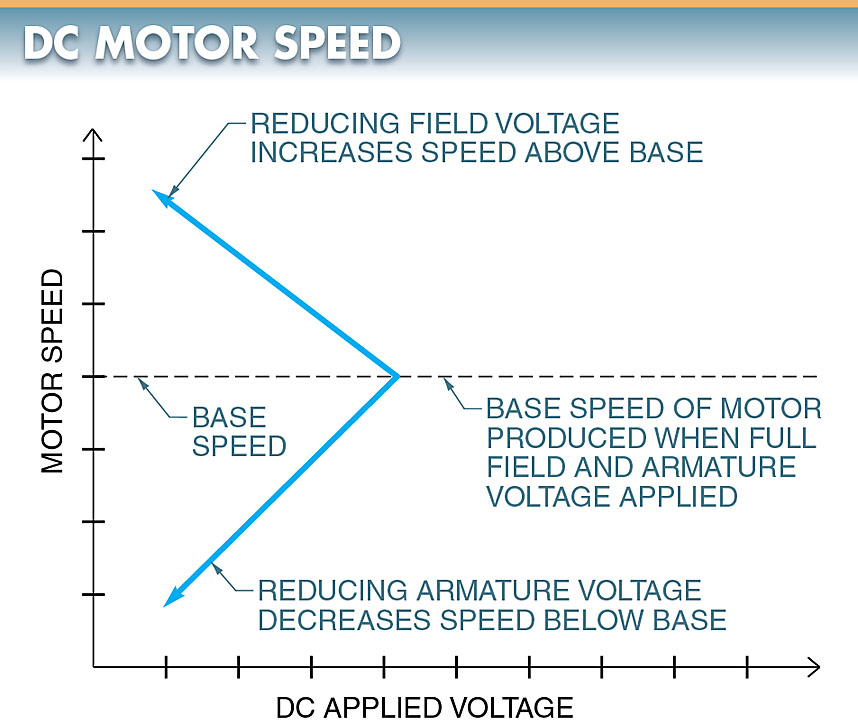
Figure 7. The speed of a DC motor is controlled by varying the applied voltage across the armature and/or field.
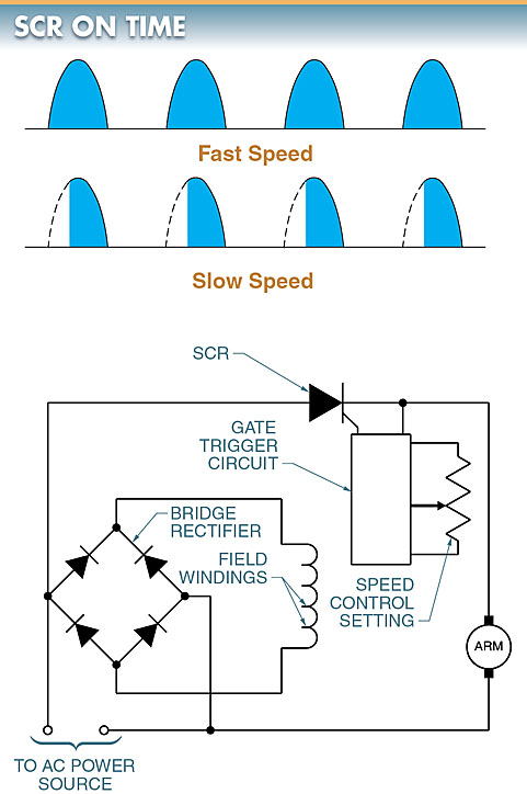
Figure 8. An SCR is used to control the speed of a DC motor.
The voltage applied to the SCR is AC voltage because the SCR rectifies (as well as controls) AC voltage. A rectifier circuit is required for the field circuit because the field circuit must be supplied with DC.
If speed control above the base is required, the rectifier circuit in the field can also be changed to an SCR control.
Stud-Mounted SCRs
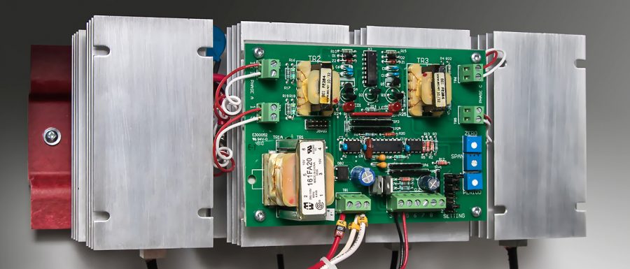
Stud-mounted SCRs are installed using the same procedure used for mounting stud-mounted diodes. Manufacturer specifications should be followed for SCR installation.
Typically, stud-mounted SCRs are fastened to heat sinks to ensure good heat flow. See Figure 9.
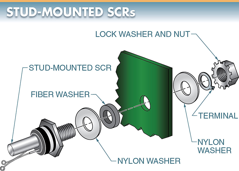
Figure 9. SCRs, like regular silicon diodes, can be stud-mounted.
SCR Testing
An oscilloscope is needed to properly test an SCR under operating conditions. A rough test using a test circuit can be made using a DMM. See Figure 10. To test an SCR using a DMM, the following procedure is applied:
- Set the DMM on the Ω scale.
- Connect the negative lead of the DMM to the cathode.
- Connect the positive lead of the DMM to the anode. The DMM should read infinity.
- Short-circuit the gate to the anode using a jumper wire. The DMM should read almost 0 Ω. Remove the jumper wire. The low resistance reading should remain.
- Reverse the DMM leads so that the positive lead is on the cathode and the negative lead is on the anode. The DMM should read almost infinity.
- Short-circuit the gate to the anode using a jumper wire. The resistance on the DMM should remain high.
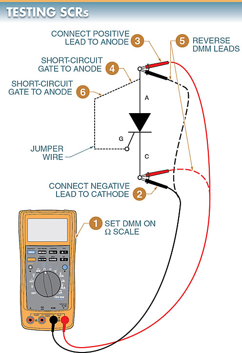
Figure 10. A rough test using a test circuit can be made on an SCR using a DMM.
