Optical Fiber is a length of ultra-pure glass or plastic that provides a closed pathway for transmitting light between two points. Glass optical fibers are by far the most commonly used, so we will assume that the optical fibers in all our discussions are made of glass.
Optical Fiber: A length of ultra-pure glass or plastic that provides a closed pathway for transmitting light between two points.
A Fiber Optic Cable contains an optical fiber that is surrounded by a layer of glass called Cladding, as shown in Figure 1. The cladding has reflective properties that help keep the light in the core of the fiber. The optical fiber and cladding are surrounded by Buffer Coating that is similar to the insulation surrounding a wire: The buffer coating protects the optical fiber from water and mechanical stresses.
Fiber Optic Cable: A cable containing an optical fiber that is surrounded by a layer of glass called cladding.
Cladding: Glass that has reflective properties that help keep the light in the core of an optical fiber.
Buffer Coating: A coating that protects an optical fiber from water and mechanical stresses.
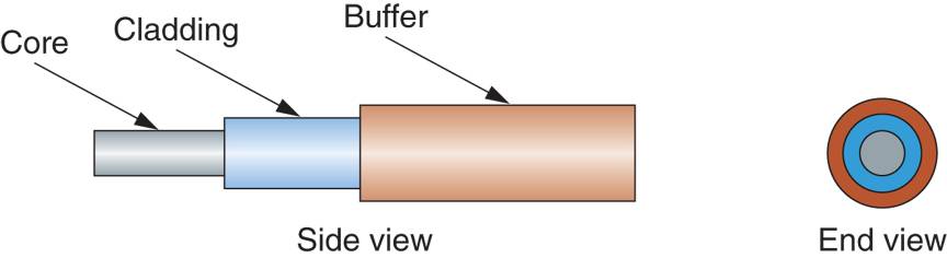
Figure 1: Parts of a Fiber-optic Cable
Types of Optical Fiber
There are essentially two types of optical fiber: single-mode and multimode. A single mode fiber is one with a diameter so narrow that it provides only one path (or mode) for light to pass through the cable. For example, one type of single mode fiber has a core diameter of only 7.9. A multimode fiber is one with a diameter large enough to provide multiple paths (modes) for light to pass through the cable. A single mode fiber, on the other hand, is so narrow that it can pass only one light signal. Multimode cables, even those having relatively small diameters, can support many modes. For example, one type of fiber with a core diameter of only 50 can support over 1000 modes.
Mode: A path of light through an optical fiber.
Single-Mode Buffer: one with a diameter so narrow that it provides only one path, or mode, for light to pass through the cable.
Multimode Fiber: One with a diameter large enough to provide multiple paths (modes) for light to pass through the cable.
Reflection in Optical Fiber
When light enters the core of an optical fiber at an angle, it strikes the cladding. Because of the cladding’s high index of refraction, its surface acts as a reflective surface. As with any reflective surface, the angle of reflection (θI). However, a point can be reached where the angle of incidence is so great that most of the light is no longer reflected. Instead, the light enters the Cladding where it is absorbed in Figure 2. The angle of incidence at which this occurs is called the Critical Angle.
Critical Angle: The angle of incidence where most of the light is an optical fiber enters the cladding rather than being reflected back into the core of the fiber.
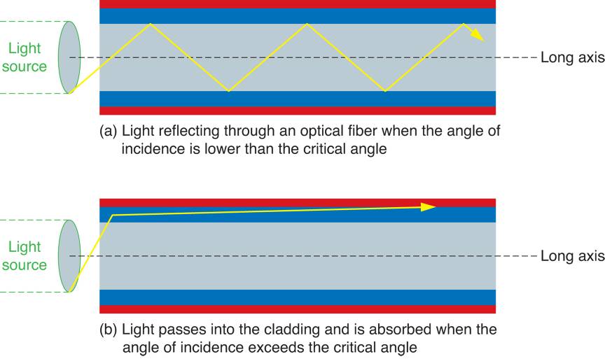
Figure 2: Fiber optic critical angle.
A Basic Fiber Optic Telecommunication System
A fiber optic telecommunication system can be broken down into three primary components:
• A light source at the transmitting end
• The fiber optic cable
• A light detector at the receiving end.
This system is represented by Figure 3. Here’s how it works. In most cases, the transmitter converts (encodes) information to strings of ones and zeros. These ones and zeros are transmitted through the fiber optic cable as a series of light pulses. Finally, the receiver accepts the information and decodes it. This process is illustrated in Figure 4.
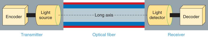
Figure 3: A fiber optic telecommunication system
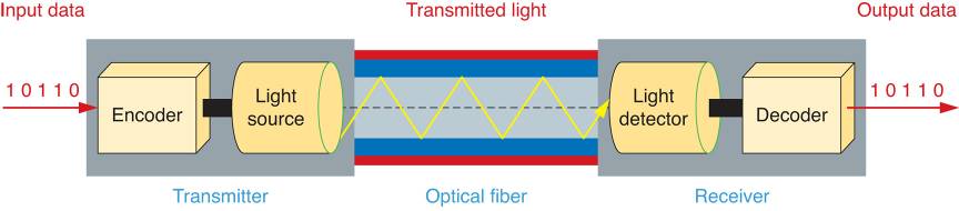
Figure 4: Data transfer through a fiber optic system.
A fiber optic system has several advantages over the copper communications systems. Specifically, fiber optic cables and systems:
1. Are not susceptible to electronic interference (EMI) or cross-talk like other telecommunications systems.
2. Can transmit much more information with far fewer errors than other telecommunications systems.
3. Are more secure than copper-based telecommunications systems.
Despite the advantages that a fiber optic system has over other telecommunications media, it is not without its own issues. We’ll take a look at one of those issues now.
Attenuation
The ideal optical fiber would be structurally perfect, allowing light signals to pass without any negative effects. The idea optical fiber, however, does not exist. Impurities left over from the manufacturing process cause a loss of light intensity (attenuation). The attenuation of a light signal as it passes through the fiber optic cable occurs when the light strikes impurity molecules in the fiber. When light hits an impurity molecule, one of two things happens:
1. The light reflects off the impurity molecule and heads in an unpredictable direction. This process, is known as Scattering, is illustrated in Figure 5.
2. The molecule absorbs energy from the light and releases it I the form of heat. This phenomenon, known as absorption, is illustrated in Figure 6.
Of the two, scattering is the great source of light attenuation in fiber optic cables.
Scattering: the phenomenon in which light reflects off an impurity molecule in an optical fiber and heads in an unpredictable direction.
Absorption: The phenomenon in which an impurity molecule absorbs energy from the light and releases it in the form of heat.
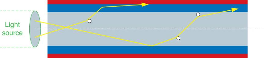
Figure 5: Scattering
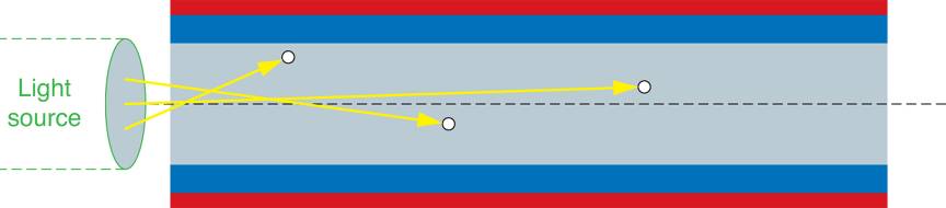
Figure 6: Absorption
The effects of both scattering absorption are more pronounced at some light wavelengths than at others. This point is illustrated by the graph shown in Figure 7.
Figure 7 shows that the attenuation caused by scattering decreases as wavelength increases frequency decreases, and that attenuation caused by absorption is significant over specific wavelength ranges that center on 1000nm, 1200 nm, and 1600nm. Little absorption occurs outside the ranges shown in the figure.
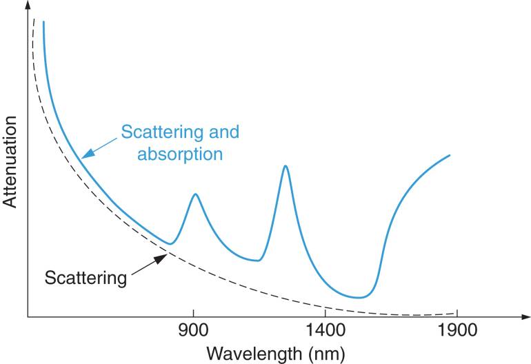
Figure 7: Attenuation in an optical fiber.
Putting It All Together
An optical fiber is a length of ultra-pure glass or plastic that provides a closed pathway for transmitting light between two points. Though sometimes made of plastic, optical fibers are far more often made of glass.
The center of a fiber optic is called the core. The glass that surrounds the core, called the cladding, has a reflective surface. Light entering the core at an angle is reflected back into the core by the cladding, provided the angle of incidence is lower than the critical angle rating of the cable.
As light passes through an optical fiber it loses some intensity (power) through attenuation. The primary causes of attenuation in a fiber optic cable are scattering and absorption. Scattering is the redirecting of light that occurs when light waves hit impurity molecules in the optical fiber. Absorption is the loss of light energy that occurs when impurity molecules absorb that energy and convert it to heat. Of the two, scattering is the primary cause of attenuation in fiber optic cables.
Summary
- An optical fiber contains a central fiber of glass surrounded by another layer of glass (called the cladding) with a higher refractive index. Around the cladding is a buffer coating that protects the fiber.
- A mode refers to a path for light in a fiber optic cable. Single-mode fibers allow a single path for light while multimode fibers allow multiple paths for light.
- The critical angle is the angle of incidence at which light is not reflected by the cladding. If θi is greater than the critical angle, light enters the cladding and is not reflected.
- The three primary components are the transmitter, which contains an encoder and a light source, the optical fiber, and a receiver, which contains a decoder and a light detector.
- Fiber optic cable is not susceptible to EMI, it has a higher data capacity, and is more secure than copper cables.
- a. Attenuation refers to a loss of light intensity as a result of impurities in the fiber.
b. Scattering is when light reflects off impurities in the glass.
c. Absorption is when light energy is absorbed by the impurities in the glass. - Scattering decreases as frequency increases. The combined effect of scattering and absorption varies with frequency, but not in a constant manner. See the graph below.
