
Flip-flops are a rather unique digital device based upon the operation of combined logic gates. Flip-flops are an essential part of digital electronics. They are at the very heart of counters, timers, sequencing devices, and memories.
Flip-flops are semiconductor devices that are capable of assuming one of two stable states. Two common flip-flops types are the R-S and the J-K varieties.
R-S flip-flop
Look at Figure 1. Two NAND and two NOT gates have been configured to operate as a flip-flop. Two NOR gates have also been configured as a flip-flop.
The standard pin markings are R, S, Q, and $\overline{Q}$ . $\overline{Q}$ is pronounced “Q not”. This flip-flop configuration is called a set-reset flip-flop, or R-S flip-flop. The S pin is called set and the R pin is called reset.
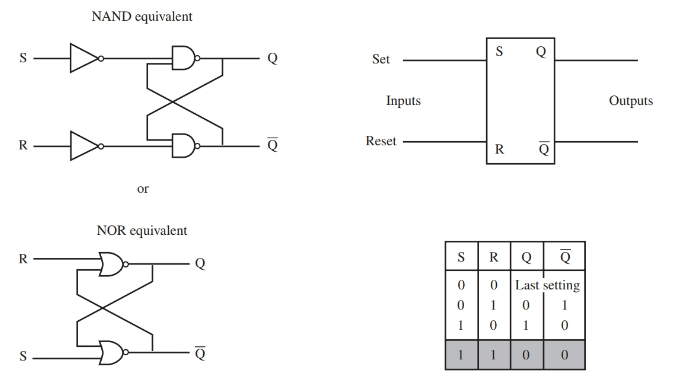
Figure 1. Typical R-S flip-flop, truth table, and two equivalent flip-flop circuits. The shaded area in the truth table indicates a not-valid condition.
The operation of an R-S flip-flop is simple. When S is high, $\overline{Q}$ is also high. When R is high, Q is high. When both inputs are low, the output will represent the last input setting. Both inputs being high is not a valid value. The output cannot be determined if both inputs are high.
Figure 1 also shows a truth table of the R-S flip-flop. The basic principle behind the operation of a flip- flop is that the outputs are complementary. To say that two outputs are complementary means that when one output is high, the other is low. Flip-flops can retain their output condition.
A clocked R-S flip-flop uses a clock to synchronize the outputs. See Figure 2. With a clocked R-S Flip-flop, the output changes when there is a change in the R or S input and a pulse appears at the clock input.
By using devices that are clock driven, millions of parts can work together in unison to form an entire digital system. A digital clock is a string of pulses that varies continuously from high to low. The pulse train is the heartbeat of most digital systems.
The R-S flip-flop retains its output status even after the input is removed. This makes the clocked R-S flip- flop a good memory device.
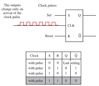
Figure 2. Clocked R-S flip-flop and truth table. The shaded area in the truth table indicates a not-valid condition.
J-K flip-flop
The J-K flip-flop is operationally similar to the R-S flip-flop. The J-K flip-flop is clock driven like the clocked R-S flip-flop. The difference is that the J-K flip-flop will retain its output status when two lows are present at its inputs. Also, when both inputs are high, the outputs will toggle on and off. See Figure 3.
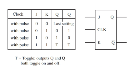
Figure 3. With the J-K flip-flop, if both data inputs are high, the outputs toggle on and off.
D flip-flop
The D flip-flop, Figure 4, is similar to the J-K flip-flop except the D flip-flop does not require two inputs and the J-K does.
When an input signal is received at the input, the Q outputs will toggle after a clock signal is applied. The output state of Q and $\overline{Q}$ will not change state until the clock signal is received.
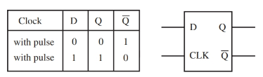
Figure 4. The D flip-flop and truth table.
By comparing the truth tables of the R-S, J-K, and D flip-flops you can see that the D flip-flop never has an unknown state, unlike the R-S and J-K.
The R-S flip-flop has a not allowed state, and the J-K flip-flop has an output state that cannot be determined unless the prior state of the flip-flop is known. D flip-flops do not have these problems.
D flip-flop output Qs are always complementary. The J-K flip-flop can be made to simulate a D flip-flop by placing a NOT gate between its inputs.
Many flip-flops are used in binary counters. As you can see, the R-S, clocked R-S, D flip-flop, and the J-K flip-flop all have at least one of the two outputs high. They switch between these two states. Q is either high or low. Since the binary number system is composed of only 0s and 1s, you can see how the flip-flops might easily be used as the heart of a binary counting system.
