The diac is a two-terminal three-layer bi-directional trigger device. It is a thyristor device but does not have a gate terminal. The diac was developed specifically as a trigger device to provide bi-directional trigger pulses.
The construction of a diac is complex and beyond the scope of this book. The symbol is shown in Figure 1.
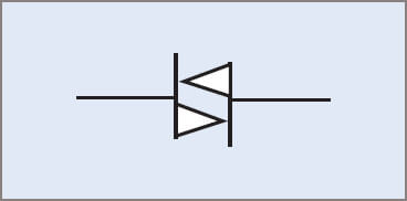
Figure 1 Diac graphic symbol
Since the diac is a bi-directional device it has no terminal markings.
DIAC Operation
Like other thyristor devices, a diac will block current flow in either direction. It is switched to the on state by exceeding the blocking voltage in either direction.
The break-over voltage for a given diac is fixed. Usually this value is the same in either direction and will be in the range 28 to 36 V. Once the diac conducts, it will remain in the on state until the current falls below the holding current.
DIAC Characteristics
From the V–I characteristics curve shown in Figure 2 it may be seen that the voltage drop across a conducting diac is much lower than the break-over voltage and is a relatively constant value. The on resistance of the diac is a very low value, like that of the PUT.
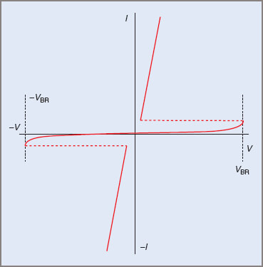
Figure 2 Diac characteristics curve (symmetrical diac)
Diacs with the same break-over voltage in either direction are referred to as ‘symmetric diacs’. The ST2 diac is a symmetric diac.
In some cases a symmetric diac results in asymmetric load voltages. For this reason, an asymmetric diac has been developed. The break-over voltages are not the same in this case. In one direction the break-over voltage is in the range 7–9 V and in the opposite direction 14 to 18 V. The ST4 is an asymmetric diac.
DIAC Relaxation Oscillator Operation
The bi-directional nature of the diac allows trigger pulses of both polarities to be produced. This is achieved by connecting the diac to an RC timing circuit and to an AC supply.
The operation of the circuit in Figure 3 may be summarized as follows:
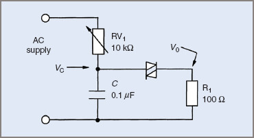
Figure 3 Diac trigger circuit
- As one terminal of the supply becomes positive and increases in potential, the capacitor charges up.
- When the capacitor voltage is equal to the break-over voltage of the diac, the diac will turn on, allowing the capacitor to discharge through the load, which is usually the gate of a thyristor.
- The diac will turn off when the capacitor is almost fully discharged. The cycle then recommences. The rate at which the capacitor changes is determined by the value of the capacitor and RV1.
- At the end of the cycle the supply will reverse and the circuit will operate in the same manner but with reverse polarity. This produces output pulses of the opposite polarity.
- With this circuit it may be possible to obtain multiple trigger pulses in each half of the AC cycle.
The waveforms produced by this circuit are shown in Figure 4.
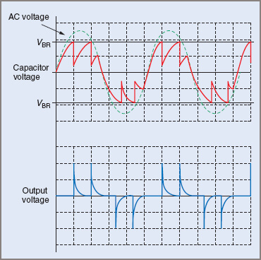
Figure 4 Diac trigger circuit waveforms
The output pulses from the diac trigger circuit are much the same as the UJT and PUT trigger circuits. The major difference is that the pulses produced alternate in polarity, or are bi-directional. This makes the diac ideal for situations where bi-directional trigger pulses are required, as in many triac load-control circuits.
