In a given single-phase AC transformer, whether auto, isolation, or current type, there are three principle transformer ratios: the current ratio, the turns ratio, and the voltage ratio. The ratios of both current and voltage are dependent on the turns ratio, which is established at the point of manufacture (by the number of wraps of wire in each respective winding).
The number of turns or wraps of wire around the iron core determine the voltage rating of a transformer or its respective circuit windings. Wrapping or coiling the wire effectively creates an inductive reactor (coil) in either the primary or secondary circuit. Instead of rating the respective coils of wire in terms of inductive reactance, the coils (windings), as used here, are rated in terms of voltage.
The voltage rating of the respective circuits in Figure 1 is determined by the number of turns or wraps of wire that each contains.
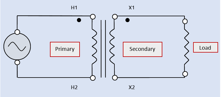
Figure 1. a single-phase transformer, and its connected load in an electrical schematic
If either the primary or secondary circuit has a high-value voltage rating, it will also have a high number of turns within the transformer winding. If either the primary or secondary circuit has a low-value voltage rating, it will also have a low number of turns within the transformer winding. The voltage and turns ratios are directly proportional to each other. By formula:
$\frac{{{V}_{P}}}{{{V}_{S}}}=\frac{{{N}_{P}}}{{{N}_{S}}}$
Where
V ( ) = the voltage rating in the primary (P) and secondary (S) circuits
N ( ) = the number of turns in the primary (P) and secondary (S) circuits
When a transformer is used for step-down of the supply voltage, the ratio of the primary-to-secondary voltage, which is equal to the turns ratio of the transformer (directly proportional), is expressed as some multiple to 1:
Example: If a step-down transformer has a voltage ratio of 30 to 1, the turns ratio is expressed as 30-to-1 (30:1).
When a transformer is used for step-up of the supply voltage, the ratio of the primary-to-secondary voltage, which is equal to the turns ratio of the transformer, is expressed as a value of 1 to some multiple of 1.
Example: If a step-up transformer has a voltage ratio of 1 to 55, the turns ratio is expressed as 1-to-55 (1:55).
When a transformer is used for isolation, the primary and secondary voltage ratings are equal. Because of the single power rating for both circuits, the primary and secondary number of turns must also be equal. The turns ratio is expressed as 1-to-1 (1:1).
Ignoring transformer core losses: The power rating of a transformer is equal to either the product of the primary-circuit voltage and current or to the product of the secondary-circuit voltage and current.
The magnitude of the currents flowing in the respective circuits of the transformer is governed by the magnitude of the load current connected to the secondary circuit.
The power rating of the transformer indicates the maximum amount of power that can be drawn by the load without seriously overheating the transformer. By formula (at 100% efficiency — assumed for all calculations):
VP × AP = VS × AS
Where
V ( ) = the voltage rating of the primary (P) and secondary (S) circuits
A ( ) = the full-load current rating of the primary (P) and secondary (S) circuits
The fact that the transformer has only one power rating for both the primary and secondary circuits sets the voltage ratio and the current ratio of the same transformer inversely-proportional to each other. Rearranging the above formula,
$\frac{{{V}_{P}}}{{{V}_{S}}}=\frac{{{A}_{S}}}{{{A}_{P}}}$
When a transformer is used for step-down of the supply voltage, the primary current is stepped up to a higher (larger) value of secondary current. The ratio of primary-to-secondary voltage is expressed as some multiple to 1. The ratio of primary-to-secondary current is expressed as a value of 1 to some multiple to 1.
Example: If a step-down transformer has a voltage ratio of 30-to-1 (30:1), its current ratio is 1-to-30 (1:30).
The current in the primary circuit of this transformer (because the voltage and current ratios are inversely proportional) will always equal the measured value of secondary current divided by 30.
When a transformer is used for step-up of the supply voltage, the primary current is stepped down to a lower (smaller) value of secondary current. The ratio of primary-to-secondary voltage is expressed as a value of 1 to some multiple of 1. The ratio of primary-to-secondary current is expressed as some multiple to 1.
Example: If a step-up transformer has a voltage ratio of 1 to 55 (1:55), its current ratio is 55-to-1 (55:1).
The current in the primary circuit of this transformer will always equal the measured value of secondary current multiplied by 55.
When a transformer is used for isolation, the primary and secondary voltage ratings are equal. Because of the single power rating for both circuits, the primary and secondary currents must also be equal. Both the voltage ratio and the current ratio are 1-to-1 (1:1).
Technically, the primary of a single transformer can be either winding. The secondary can be either winding. The primary winding is connected to the power source that is being transformed (stepped down for a lower-circuit voltage, stepped up for a higher-circuit voltage, or merely electrically isolated for the same circuit voltage). The secondary winding is connected to the load the transformer is supplying power to.
The actual secondary load current of the transformer may be well under its full-load capability (for example, 200 amps available, but only a 60-amp load is connected to the transformer). By Ohm’s law, the magnitude of the secondary-circuit current is determined by the secondary-circuit voltage rating and the resistance (or AC impedance) of the connected load: The higher the secondary-circuit resistance, the lower the load current, and vice versa. The actual primary-circuit current value will always be in direct proportion to the actual secondary load current (neglecting transformer losses).
The ratios of voltage, current, and number of turns will hold true for any transformer, whether it is rated as a small signaling transformer (such as a common doorbell supply), a small power transformer (as shown in the previous example), or a large power transformer (often found in unit substations).
