
Electromechanical relays (EMRs) and Solid state relays (SSRs) are designed to provide a common switching function. An EMR provides switching through the use of electromagnetic devices and sets of contacts. An SSR depends on electronic devices such as SCRs and triacs to switch without contacts.
In addition, the physical features and operating characteristics of EMRs and SSRs are different. See Figure 1.
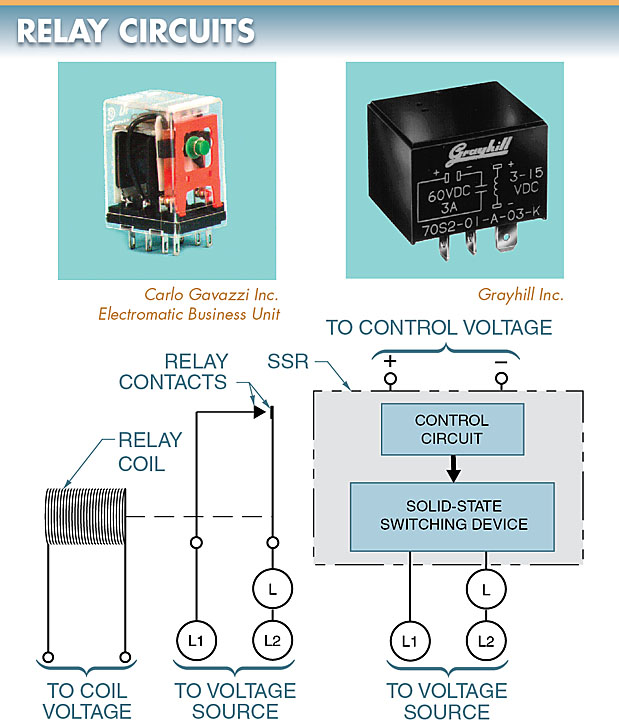
Figure 1. An Electromechanical relay provides switching using electromagnetic devices. A solid state relay depends on SCRs and triacs to switch without contacts.
An equivalent terminology chart is used as an aid in the comparison of EMRs and SSRs. Because the basic operating principles and physical structures of the devices are so different, it is difficult to find a direct comparison of the two.
Differences arise almost immediately both in the terminology used to describe the devices and in their overall ability to perform certain functions. See Figure 2.
Advantages and Limitations
Electromechanical relays and solid state relays are used in many applications. The relay used depends on the electrical requirements, cost requirements, and life expectancy of the application.
Although SSRs have replaced EMRs in many applications, EMRs are still very common. Electromechanical relays offer many advantages that make them cost-effective. However, they have limitations that restrict their use in some applications.
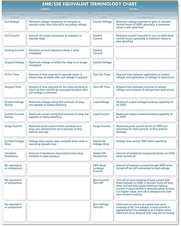
Figure 2. An equivalent terminology chart is used as an aid in the comparison of EMRs and SSRs.
Electromechanical relay advantages include the following:
- normally have multi-pole, multi-throw contact arrangements
- contacts can switch AC or DC
- low initial cost
- very low contact voltage drops, thus no heat sink is required
- very resistant to voltage transients
- no OFF-state leakage current through open contacts
Electromechanical relay limitations include the following:
- contacts wear, thus having a limited life
- short contact life when used for rapid switching applications or high-current loads
- generate electromagnetic noise and interference on the power lines
- poor performance when switching high inrush currents
SSRs provide many advantages such as small size, fast switching, long life, and the ability to handle complex switching requirements. SSRs have some limitations that restrict their use in some applications.
Solid state relay advantages include the following:
- very long life when properly applied
- no contact to wear
- no contact arcing to generate electromagnetic interference
- resistant to shock and vibration because they have no moving parts
- logic compatible with programmable controllers, digital circuits, and computers
- very fast switching capability
- different switching modes (zero switching, instant- on, etc.)
Solid state relay limitations include the following:
- normally only one contact available per relay
- heat sink required due to the voltage drop across switch
- can switch only AC or DC
- OFF-state leakage current when the switch is open
- normally limited to switching only a narrow frequency range such as 40 Hz to 70 Hz
Input Signals
The application of voltage to the input coil of an electromagnetic device creates an electromagnet that is capable of pulling in an armature with a set of contacts attached to control a load circuit. It takes more voltage and current to pull in the coil than to hold it in due to the initial air gap between the magnetic coil and the armature.
The specifications used to describe the energizing and de-energizing process of an electromagnetic device are coil voltage, coil current, holding a current, and drop-out voltage.
A solid state relay has no coil or contacts and requires only minimum values of voltage and current to turn it on and off. The two specifications needed to describe the input signal for an SSR are control voltage and control current.
The electronic nature of an SSR and its input circuit allows easy compatibility with digitally controlled logic circuits. Many SSRs are available with minimum control voltages of 3 V and control currents as low as 1 mA, which makes them ideal for a variety of current state-of-the-art logic circuits.
Response time
One of the significant advantages of a solid state relay over an electromechanical relay is its response time (ability to turn on and turn off). An EMR may be able to respond hundreds of times per minute, but an SSR is capable of switching thousands of times per minute with no chattering or bounce.
DC switching time for an SSR is in the microsecond range. AC switching time for an SSR, with the use of zero-voltage turn-on, is less than 9 ms. The reason for this advantage is that the SSR may be turned on and turned off electronically much more rapidly than a relay may be electromagnetically pulled in and dropped out.
The higher speeds of solid state relays have become increasingly more important as industry demands higher productivity from processing equipment. The more rapidly the equipment can process or cycle its output, the greater its productivity.
Voltage and Current Ratings
Electromechanical relays and solid state relays have certain limitations that determine how much voltage and current each device can safely handle. The values vary from device to device and from manufacturer to manufacturer. Datasheets are used to determine whether a given device can safely switch a given load.
The advantages of SSRs are that they have a capacity for arc-less switching, have no moving parts to wear out, and are totally enclosed, thus allowing them to be operated in potentially explosive environments without special enclosures.
The advantage of EMRs is that the contacts can be replaced if the device receives an excessive surge current. In an SSR, the complete device must be replaced if there is damage.
Voltage Drop
When a set of contacts on an electromechanical relay closes, the contact resistance is normally low unless the contacts are pitted or corroded. However, because an SSR is constructed of semiconductor materials, it opens and closes a circuit by increasing or decreasing its ability to conduct.
Even at full conduction, a solid state relay presents some residual resistance, which can create a voltage drop of up to approximately 1.5 V in the load circuit. This voltage drop is usually considered insignificant because it is small in relation to the load voltage and in most cases presents no problems. This unique feature may have to be taken into consideration when load voltages are small.
A method of removing the heat produced at the switching device must be used when load currents are high.
Insulation and leakage
The air gap between a set of open contacts provides an almost infinite resistance through which no current flows. Due to their unique construction, solid state relays provide a very high but measurable resistance when turned off. SSRs have a switched-off resistance not found on EMRs.
It is possible for small amounts of current (OFF-state leakage) to pass through an SSR because some conductance is still possible even though the SSR is turned off. OFF-state leakage current is not found on EMRs.
OFF-state leakage current is the amount of current that leaks through an SSR when the switch is turned off, normally about 2 mA to 10 mA. The rating of OFF-state leakage current in an SSR is usually determined at 200 VDC across the output and should not usually exceed more than 200 mA at this voltage.
