The overhead line conductors are open and do not have any insulated coating over them. Those conductors should be supported on the poles or towers in such a way that current from conductors does not flow to earth through supports, that is, line conductors must be properly insulated. This is accomplished by connecting line conductors to a support with the help of insulators.
The insulator provides necessary insulation between line conductors and supports and thus prevents any leakage current from conductors to ground. Insulators also provide support to the conductor.
Overhead Line Insulator Properties
In general, the insulator should have the following desirable properties:
- High mechanical strength in order to withstand conductor load, wind load, etc.
- The high electrical resistance of insulator material in order to avoid leakage current to earth.
- The high relative permittivity of insulator material in order that dielectric strength is high.
- The insulator material should be nonporous, free from impurities, otherwise, permittivity will be lowered.
- The high ratio of puncture strength to flashover.
Overhead Line Insulator Materials
The following three materials are widely used in the manufacture of insulator units:
- Porcelain
- Glass
- Synthetic resin
The most commonly used materials for the overhead line is porcelain. Porcelain is a ceramic material. It is produced by firing at a high temperature a mixture of kaolin, feldspar, and quartz.
The metal parts within the insulator are made of malleable cast iron with galvanizing. It is mechanically stronger than glass, gives less trouble from leakage, and is less affected by temperature change.
A glass is also used as an insulator material instead of porcelain. However, glass insulators are mainly used for EHV AC and DC systems.
The glass is toughened by heat treatment. Though it is more brittle, its transparency, cracks, and defects within the insulator material can be detected easily by visual inspection.
The glass insulators, on the other hand, are disadvantageous from the point of view that moisture condensation is more likely on the insulator surface causing higher leakage of current.
Synthetic insulators are mostly used in various indoor applications. They contain compounds of silicon, rubber, resin, etc.
Synthetic insulators have high strength and lower weight. However, the leakage current is higher and longevity is low. On the other hand, they are comparatively cheaper and have applications in bushings mainly.
Types of Overhead Line Insulators
Various types of insulators used for overhead transmission and distribution lines are described below.
1 Pin-Type Insulators
The part section of a pin-type insulator is shown in Figure 1. As the name suggests, the pin-type insulator is secured to the cross-arm on the pole.
There is a groove on the upper end of the insulator for housing the conductor. The conductor passes through this groove and is bound by the annealed wire of the same material as that of the conductor.
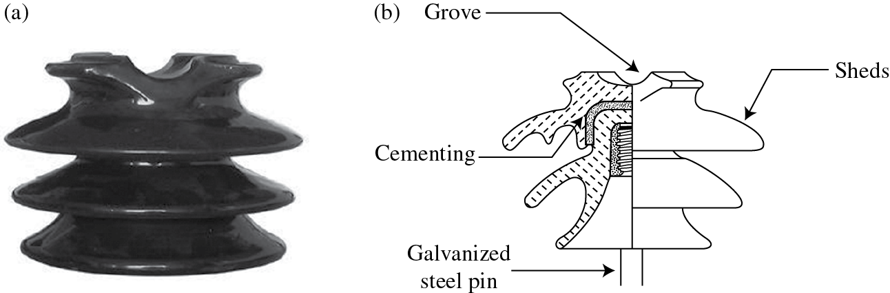
Figure 1: (a) Pin-type insulator and (b) cross-sectional view of pin-type insulator.
Pin-type insulators are used for transmission and distribution of electric power at voltages up to 33 kV. Beyond operating voltage of 33 kV, pin-type insulators become too bulky and hence uneconomical.
1.1 Causes of Insulator Failure
Insulators are required to withstand both mechanical and electrical stresses. The latter type is primarily due to line voltage and may cause breakdown of the insulator.
The electrical breakdown of the insulator can occur due to flashover or puncture.
In the flashover, an arc occurs between the line conductor and the insulator pin (i.e., earth) and the discharge jumps across the air gaps, following the shortest distance.
Figure 2 shows the arcing distance (i.e., a + b + c) for the insulator. In this case, the insulator will continue to act in its proper capacity, unless extreme heat produced by the arc destroys the insulator.
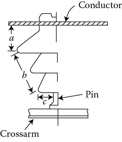
Fig. 2: Arcing distance in the insulator
In case of puncture, the discharge occurs from conductor to pin through the body of the insulator. In case of puncture, the insulator is permanently destroyed due to excessive heat.
To avoid the puncture, sufficient thickness of porcelain is provided in the insulator. The ratio of puncture strength to flashover voltage is known as the safety factor, that is,
\[Safety\text{ }Factor\text{ }of\text{ }the\text{ }Insulator=\frac{Puncture\text{ }Strength}{Flash-Over\text{ }Voltage}\]
It is desirable that the value of safety factor is high so that flashover takes place before the insulator gets punctured. For pin insulators, the value of safety factor is about 10.
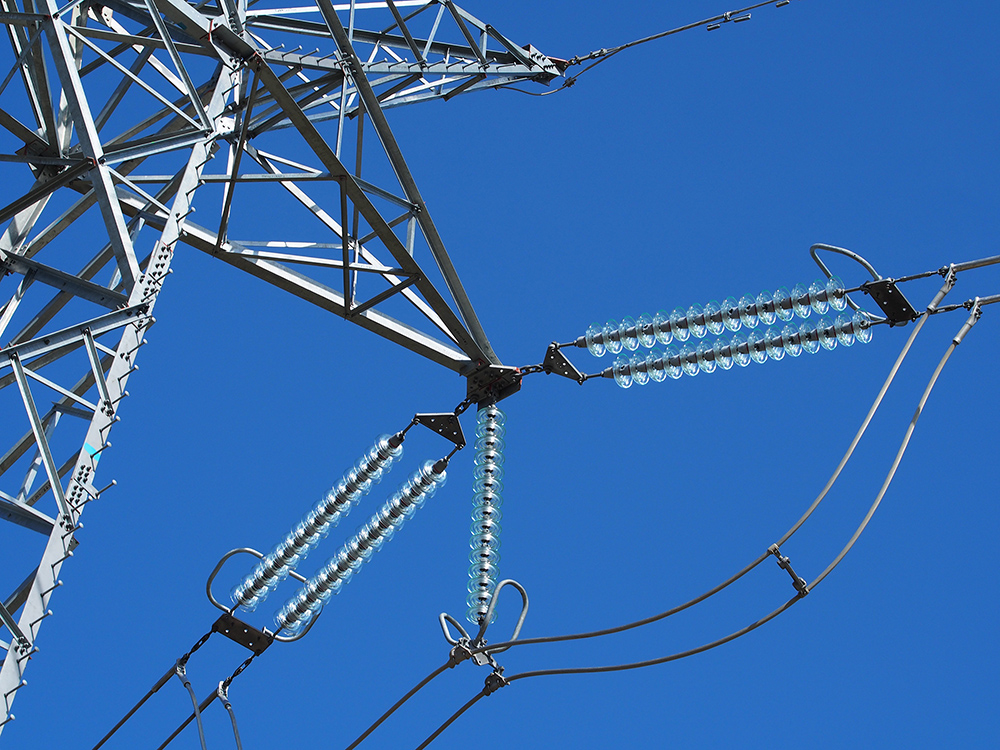
2 Suspension Type Insulators
For high voltages (>33 kV), it is a usual practice to use suspension type insulators shown in Figure 3. They consist of a number of porcelain disks connected in series by metal links in the form of a string.
The conductor is suspended at the bottom end of this string, while the other end of the string is secured to the cross-arm of the tower. Each unit or disk is designed for low voltage (say 11 kV). The number of disks would obviously depend upon the working voltage. For instance, if the working voltage in 66 kV, then six disks in series will be provided on the string.
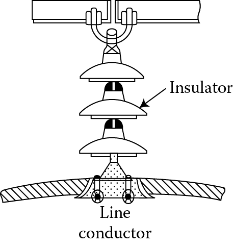
Fig. 3: Suspension type insulators.
Advantages
- Cheaper than insulators for voltages beyond 33 kV.
- Each unit or disk is designed for low voltage (say 11 kV). The number of disks would obviously depend upon the working voltage.
- If any disk is damaged, the whole string does not become useless because the damaged disk can be replaced by the sound one.
- The arrangement provides greater flexibility to the line. The connection at the cross-arm is such that insulator is free to swing in any direction and can take up the position, where the mechanical stresses are minimized.
- The suspension type insulators are generally used with steel towers. As the conductors run below the earthed cross-arm of the tower, therefore, this arrangement provides partial protection from lightning.
- In case of increased demand on the transmission line, it is found more satisfactory to supply greater demand by raising the line voltage, than to provide another set of the conductor. The additional insulation required for the raised voltage can be easily obtained in the suspension arrangement by adding the desired number of disks.
2.1 Types of Suspension Insulators
The types of suspension insulators in use are
- Cap-and-pin type
- Hewlett or interlink type
The first type is more common. A galvanized cast iron or forged-steel cap and galvanized forged-steel pin are connected to porcelain in the cap-and-pin type construction.
The units are joined together either by ball and socket or clevis–pin connections. Cap-and-pin type construction is given in Figure 4.
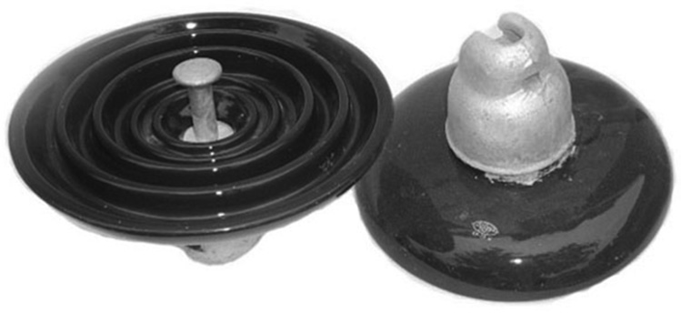
Fig. 4: Cap-and-pin type construction.
The interlink type unit (Figure 5) employs porcelain having two curved channels with planes at right angles to each other. U-shaped level covered steel links pass through these channels and serve to connect the units.
Interlink type insulator is mechanically stronger than the cap-and-pin type unit. The metal links continue to support the line if the porcelain between the links breaks. Thus, the supply is not interrupted.
The Hewlett type of insulator suffers from the disadvantage that the porcelain between links is highly stressed electrically and, therefore, its puncture strength is lesser as compared to other types.
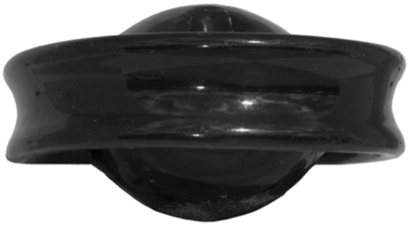
Fig. 5: Interlink type insulator.
3 Strain Insulators
When there is a dead end of the line or there is a corner or sharp curve, the line is subjected to greater tension. In order to relieve the line of excessive tension, strain insulators are used.
For low-voltage lines (<11 kV), shackle insulators are used as strain insulators. However, for high-voltage transmission lines, strain insulator consists of an assembly of suspension lines; strain insulator consists of an assembly of suspension insulators as shown in Figure 6.
The disks of strain insulators are used in the vertical plane. When the tension in the line is exceeding high, as, at long river spans, two or more strings are used in parallel.
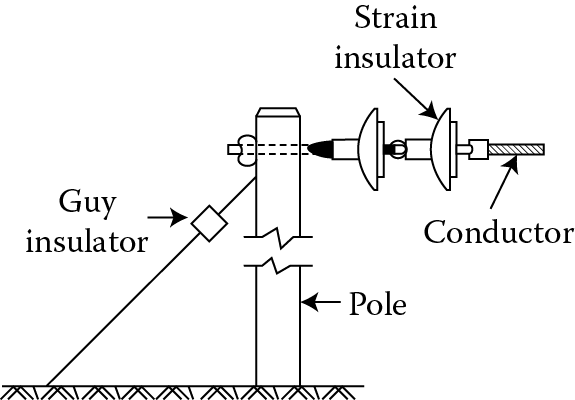
Fig. 6: Strain insulator.
4 Shackle Insulators
In early days, the shackle insulators were used as strain insulators. But nowadays, they are frequently used for low-voltage distribution lines (<11 kV). Such insulators can be used either in the horizontal position or in the vertical position.
They can be directly fixed to the pole with a bolt or to the cross-arm. Figure 7 shows a shackle insulator fixed to the pole. The conductor in the groove is fixed with a soft binding wire.
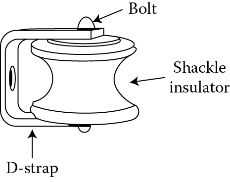
Fig: 7 Shackle insulator.
5 Stay Insulators
These kind of insulators are of egg shape, also called strain or guy insulators, and are used in guy cables, where it is very important to insulate the lower portion of the guy cable from the pole for the safety of human beings and animals on the ground.
This type of insulator comprises of a porcelain piece pierced with two holes at right angles to each other through which two ends of the guy wires are looped. This compresses the porcelain between the two loops in and the guy wire remains in the same position even if the insulator breaks due to any reason. Figure 8 shows a stay insulator.
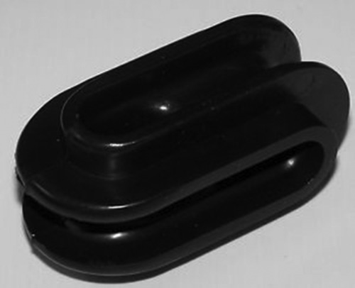
Fig: 8: Stay insulator.
