Electrical power systems used in buildings may be divided into three voltage classes. The system voltage is defined as the voltage between lines, or line-to-line voltage.
- Extra-low-voltage systems (50 V and below) This class is normally used for control, signal, and communication systems.
- Low-voltage systems (nominally below 600 V) The practical range in the United States is between 120 and 600 V. In commercial use, 120–250 V have been known as low-voltage systems, and 480–600 V as medium-voltage systems; however, strictly speaking, the National Electrical Code (NEC) considers all systems up to 600 V low-voltage systems. This class is normally used for supplying lighting and power equipment, except for extremely large equipment such as a single 1000-hp motor.
- Medium-voltage systems (600 to 100,000 V) The practical range in the United States is 2300–69,000 V. This class is normally used to supply distribution transformers with step-down voltages to building distribution systems and equipment loads. Voltages of 13,800 and below are also used to supply large motors.
High-voltage systems (greater than 100,000 V) are not normally used in buildings.
There are variations within each voltage class. For power distribution within buildings, low-voltage systems up to 480 V are most common.
Medium- and high-voltage systems are used only in large buildings with several million square feet in floor area or in industrial plants.
Table 1 lists the differences between system and equipment voltages of common power distribution systems. Note that nominal system voltages are higher than nominal equipment voltages.
Even with the best-designed systems, the voltage of a power distribution system will unavoidably drop between its supplying end (source) and receiving end (load), owing to the impedance inherent in the distribution components. For this reason, equipment or appliance voltage ratings are usually about 5 percent lower than system voltage ratings.
For example, single-phase electrical appliances are usually rated for 110 to 115 V for use on the 120 to the 125-V system in the United States. Similarly, 460-V motors are used on 480-V three-phase systems.
Table 1: Voltage Rating of Common Distribution Systems Showing the System versus Equipment Voltages and the Maximum Equipment Rating versus the System Capacity. In General, the Maximum Rating of a Single Piece of Inductive Load (Motor) should not Exceed 15–20% of the System Capacity if the System also Serves Other Loads
| Distribution systems | Nominal System voltage (V) | Nominal Equipment Voltage (V) | Application Limits | ||
| Max. Inductive Equipment Rating, a kVA | System Capacity, kVA | ||||
| Single Phase, Three-Wire | 120/240 | 115/230 | 20 | 100 | |
| Three Phase, Four-Wire | 120/208 | 115/200 | 150 | 750 | |
| 220/380 | 210/365 | 500 | 3000 | ||
| 277/480 | 265/460 | 500 | 3000 | ||
| 2400/4160 | 2300/4000 | 5000 | 15000 | ||
| 7200/12470 | 69000/12000 | 10000 | 50000 | ||
| 19920/34500 | N/A | N/A | No Maximum | ||
| Three Phase, Three-Wire | 240 | 230 | 150 | 750 | |
| 480 | 460 | 500 | 3000 | ||
| 600 | 575 | 500 | 3000 | ||
| 4160 | 4000 | 5000 | 15000 | ||
| 13800 | 13200 | 10000 | 50000 | ||
| 34500 | N/A | N/A | No Maximum | ||
aRefers to a single piece of the inductive load, such as a motor that can be connected on this system without causing excessive voltage dip. This is because of the extremely but momentarily large inrush of current during start-up.
The following sections give guidelines for selecting a system voltage and knowing its limitations.
Loads Less Than 100 kVA
Residential and small buildings typically have a demand load less than 100 kVA. Loads are normally rated for 120 or 240 V, single phase. Thus, a 120- to 240-V single-phase three-wire system is most appropriate. [See Fig. 1(a).]
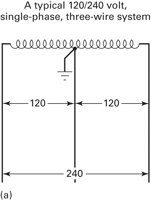
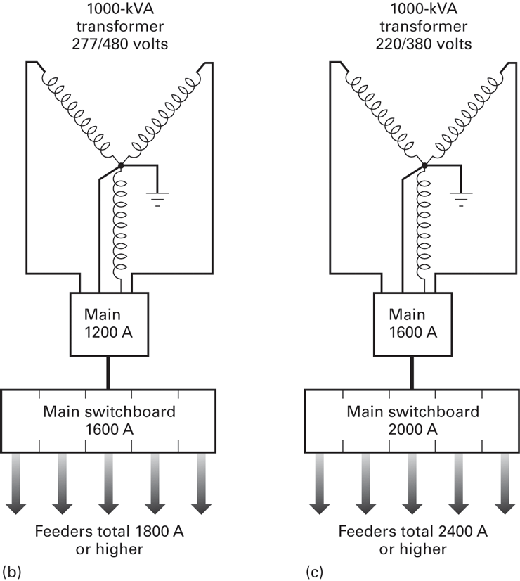
Figure 1: Three Phase Four Wire Systems
(a) One-line diagram of a 120/240-V single-phase system. Similar systems of the same voltage class include 115/230 V and 125/250 V.
(b) One-line diagram of a 1000-kVA, 277/480-V three-phase four-wire power distribution system showing its size (the capacity of the system components).
(c) 1000-kVA system identical to (b), but at 220/380 V it requires about 25% higher ampacity of its distribution components and thus a higher capital investment. More convincingly, when a 277/480-V system is compared with a 120/208-V system, the lower-voltage system will require nearly 150% more ampacity.
Loads Greater Than 100 kVA
Loads greater than 100 kVA are usually served by three-phase systems. An exception is multiunit apartments or small shopping centers, where it is entirely appropriate to use a single-phase system, even if the total load far exceeds 100 kVA.
As the load increases, systems at higher voltages are favored, owing to the economy of equipment and to the reduction of wire sizes.
Popular systems used in the United States are 120-, 120/240-, 240-V single-phase systems and 120/208-, 240-, 277/480-, and 480-V three-phase systems.
The 220/380-V systems are quite common in countries where the utilization voltage for appliances is 220 V rather than 120 V. In such a system, 220-V single-phase lines will serve small appliances, and 380-V three-phase lines will serve larger loads.
However, the 220/380-V system will eventually be replaced by a 277/480-V system, which is considerably more economical. For example, a 1000-kVA, 380-V three-phase system requires a 1600-A main service, whereas a 480-V three-phase system requires only a 1200-A main service. This 25 percent reduction in current affects the distribution equipment and feeders all the way down the line and, thus, the overall system cost. [See Fig. 1(b) and (c).]
Medium-voltage systems such as 2400/4160 V and higher voltage systems such as 7200/12,470 V are also used for buildings in which the total load exceeds the service capacity of low-voltage systems.
Common Distribution Systems
Fig. 2 provides a summary of power systems appropriate for various load capacities.
For extremely large buildings with over 1 million square feet in gross floor area, or for campus-type facilities, power distribution may consist of many small systems, all interconnected to increase the system’s flexibility and reliability.
The figure shows five primary and secondary distribution systems, ranging from simple secondary radial to the more complex primary and secondary selectives. The term primary refers to the portion of a distribution system before a transformer, and secondary indicates the portion after a transformer.
Simple Secondary Radial
The system, shown in Fig. 2(a), is the simplest of all. It usually contains a single step-down transformer that transforms the primary voltage (e.g., 4160 V) to a secondary voltage (e.g., 120–240 V) for distribution to the loads.
Typical applications of simple secondary radial systems are small office buildings, stores, and large residences. The transformers may be external to the building, or within the building, depending on need.
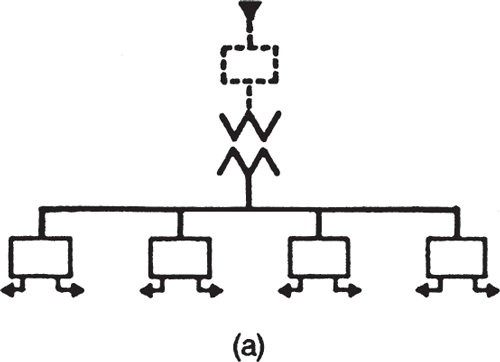
Figure 2 (a) Simple radial system
Distributed Radial
The system, shown in Fig. 2(b), consists of multiples of simple secondary radial systems.
Typical applications are shopping centers, apartment complexes, large department stores, schools, and institutional buildings.
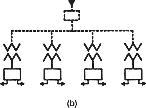
Figure 2 (b) Distributed radial system
Primary Loop
The system, shown in Fig. 2(c), consists of several simple secondary radial distribution systems having the primary feeders connected in a loop. In case a section of the primary feeder is faulty, that section of the primary feeder may be isolated and power may be fed from another direction.
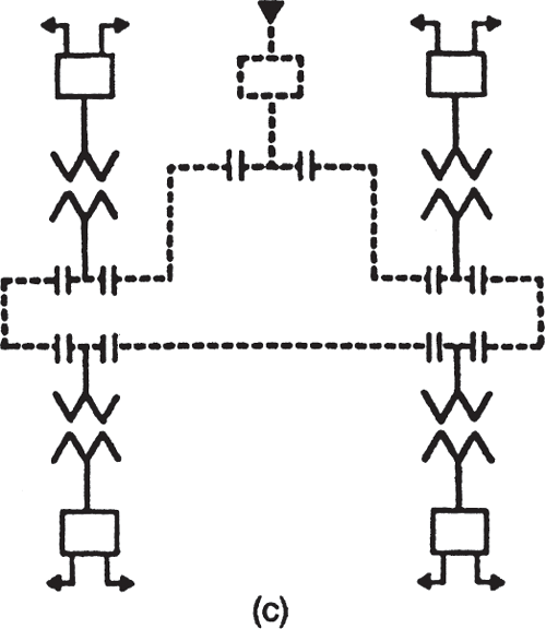
Figure 2 (c) Secondary loop system
This system is normally used in industrial plants or campus-type facilities to provide a degree of redundancy without the cost of dual primary feeders.
Primary Selective
The system, shown in Fig. 2(d), consists of dual primary feeders to each transformer substation.
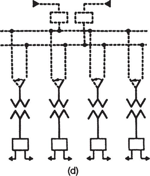
Figure 2 (d) Primary and secondary loop system
This is most commonly used in high-rise buildings, hospitals, and research facilities where reliable power is essential. The second primary power source may be either from another power source or from a group of standby generators.
Primary Loop with Secondary Tie
The system, shown in Fig. 2(e), consists of a primary loop as in Fig. 2(c) and interconnected secondary feeders between adjacent power distribution centers so that loads served by one distribution center may be back-fed from another center.
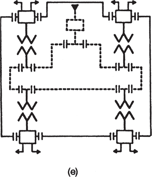
Figure 2 (e) Primary selective system
This type of system is frequently used in hospitals, research centers, and computer centers that need an additional level of reliability.
